Fluoroscopy Equipment Operation
Fluoroscopy Equipment Operation. Rad T 290. Topics for WEEK 2. Describe the components of an image intensifier. Describe the components of flat panel digital fluoroscopy. TV & viewing system…….. etc. II Fluoroscopy. The II was developed to replace the conventional fluorescent screen.

Fluoroscopy Equipment Operation
E N D
Presentation Transcript
Fluoroscopy Equipment Operation Rad T 290
Topics for WEEK 2 • Describe the components of an image intensifier. • Describe the components of flat panel digital fluoroscopy. • TV & viewing system……..etc
II Fluoroscopy • The II was developed to replace the conventional fluorescent screen. • The II raised illumination into the cone vision region, where visual acuity is greatest. • Technical factors is similar to radiographic image quality. Generally, high kVp and low mA are preferred.
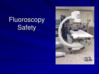
VACUUM TUBE ENCASED IN A LEAD HOUSING = 2MM PB (PRIMARY BARRIER) Image Intensifier
Input screen and photocathode Electrostatic lenses Anode and output screen Image Intensification Tube Components
Steps to image intensification • Object of the II is to convert remnant radiation into an amplified light image • 5 basic parts • Input phosphor • Photocathode • Electrostatic lenses • Accelerating anode • Output phosphor
Image intensifier component • Input screen: conversion of incident X Rays into light photons (CsI) • 1 X Ray photon creates 3,000 light photons • Photocathode: conversion of light photons into electrons • only 10 to 20% of light photons are convertedinto photoelectrons • Electrodes (lenses): focalization of electrons onto the output screen • electrodes provide the electronic magnification • Output screen: conversion of accelerated electrons into light photons
II Fluoroscopy • During image-intensified fluoroscopy, the radiologic image is displayed on a television monitor or flat panel monitor. • X-ray tube is operated at less than 5 mA. Radiographic exams the x-ray tube current is measured in hundreds of mA. • Despite this fluoro dose tends to be much higher?
kVp • KVp depends entirely on the anatomy being examined. Fluoroscopic equipment operates by selecting an image brightness. The automatic brightness control (ABC) • The ABC maintaines image brighness automatically by varying the kVp, the mA, or sometimes both. • Generally kVp is maintained by adjust the mA depending on part/patient thickness
Image-intensifier • Remnant photons enter the image-intensifier tube transmitted through the glass envelope and interact with the input phosphor, which is cesium iodide (CsI). When an x-ray interacts with the input phosphor, its energy is converted into visible light. • Where else does this occur in radiography?
Cesium Iodide microlight pipes • CsI crystals are grown as tiny needles and are tightly packed in a layer of approximately 300 µm
Input phosphor • Is a round tube that can A diameter of 6, 9, 12 or 16 inches
Photocathode • The next active element of the image-intensifier tube is the photocathode. • Bonded directly to the input phosphor with a thin, transparent adhesive layer. The photocathode is a thin metal layer composed of cesium and antimony compounds that respond to stimulation of input phosphor light by the emission of electrons. • The photocathode emits e- when illuminated by the input phosphor
Photoemission • This process is known as photoemission. • Photoemission is electron emission that follows light stimulation. • The number of electrons emitted by the photocathode is directly proportional to the intensity of light that reaches it.
Electrostatic Focusing Lenses • A series of metal rings which have varying positive voltage. • They pull the e- from the input side toward the put out phosphor. • This process is called minification.
The image intensifier (I.I.) I.I. Input Screen Electrode E1 Electrode E2 Electrode E3 Electrons Path I.I.Output Screen Photocathode +
The anode of the II The anode is a circular plate about 20” away from the photocathode. It has a hole in the middle of it allowing electrons to pass through and hit the output phosphor made of zinc cadmium sulfide. Electrostatic lenses have a negative charge to repel the negative electrons and push them to the anode and focus them to a narrow beam. The electrons are carrying the latent image and when they hit the output phosphor they are turned into light again.
Accelerating Anode • II tube is approximately 50 cm long • Potential difference between photocathode and anode of 25,000 - 30, 000 V
Flux gain (flow) • The ratio of the number of light photons striking the output screen to the ratio of the number of x-ray photons striking the input screen is called fluxgain
1000 light photons at the photocathode from 1 x-ray photon Output phosphor = 3000 light photons (3 X more than at the input phosphor!) This increase is called the flux gain FLUX GAIN
Output Phosphor • a 1” circular plate with a hole in the middle through which electrons pass. • Made of zinc cadmium sulfide that produces light by interacting with e-. • Output phosphor is always 1”. • Very concentrated bright light is direct to a TV camera tub or CCD.
Minification(↑ BRIGHTNESS OF LIGHT) Electrons had to be focused down to fit through the hole at the anode. Input phosphor is much bigger than the anode opening Input phosphors are 10-35 cm in diameter* (6, 9 , 12 inches) Output phosphors are 2.5 to 5 cm (1 in) in diameter* Most fluoro tubes have the ability to operate in 2 sizes (just like small and large focal spot sizes) Bi focus or newer units - tri focus
Total brightness gain (BG) The II makes the image brighter because it is minified and amplified (more light photons). BG = MG X FG Multiply the minification gain times the flux gain.
Intensifier Brightness Gain (BG) BG = MG x FG Minification Gain x Flux Gain • Minification gain (MG): The ratio of the squares of the input and output phosphor diameters. This corresponds to “concentrating” the light into a smaller area, thus increasing brightness MG = (Input Diameter )2 (Output Diameter)2
Minification gain - again • BG = MINIFICATION GAIN X FLUX GAIN • MINIFICATION GAIN – same # e at input condensed to output phosphor – ratio of surface area on input screen over surface area of output screen IP SIZE 2 OP SIZE 2
BG = MG X FG • FLUX GAIN – increase of light brightness due to the conversion efficiency of the output screen (estimation) • 1 electron = 50 light photons is 50 FG • Can decrease as II ages • Flux gain is almost always 50
Intensifier Brightness Gain • Example: Input Phosphor Diameter = 9” Output Phosphor Diameter = 1” Flux Gain = 50 BG = FG x MG = 50 x (9/1)2 = 4,050 • Typical values: a few thousand to >10,000 for modern image intensifiers
Intensifier Brightness Gain • Flux Gain (FG): Produced by accelerating the photoelectrons across a high voltage (>20 keV), thus allowing each electron to produce many more light photons in the output phosphor than was required to eject them from the photcathode. • Summary: Combining minification and flux gains:
Image Intensifier FORMULAS • Brightness Gain • Ability of II to increase illumination • Flux Gain (usually stated rather than calculated) • Minification Gain
Conversion Factor • International Commission of Radiologic Units and Measurements (ICRU) recommends evaluating the brightness gain of the II based upon the conversion factor.
Image Intensifier Performance Conversion factor is the ratio of output phosphor image luminance (candelas/m2) to x-ray exposure rate entering the image intensifier (mR/second). • II has conversion factors between 50 - 300 • Usually 5000 to 30,000 brightness gains
5 4 1 2 3 Image Intensifier Tube • Vacuum diode tube 1. Input phosphor (CsI) • X-rays light 2. Photocathode • Photoemission • Light electron beam 3. Electrostatic lenses • Maintain & minify e- 4. Anode • Attracts e- in beam 5. Output phosphor (ZnS-CdS) • e- light
Multifield Image Intensification • FOV selection gives you the active diameter of the input phosphor. 6, 9, 12 or 16” • In 16” mode photoelectrons from the entire input phosphor are accelerated to the output phosphor. • 12” mode, the voltage on the electrostatic focusing lenses increase causing the electron focal point to move farther from the output phosphor. Only 12’ of input phosphor are on the output phosphor.
Magnification Tubes • Greater voltage to electrostatic lenses • Increases acceleration of electrons • Shifts focal point away from anode • Dual focus • 23/15 cm 9/6 inches • Tri focus • 12/9/6 inches
Intensifier Format and Modes Note focal point moves farther from output in mag mode
FOV • This change in focal point will reduce the FOV and the image appears magnified. • Using the smaller dimension of a multifield image-intensifier tube always results in a magnified image, with a magnification factor in direct proportion to the ratio of the diameters.
Magnification Factor FORMULA IP OLD SIZE IP NEW SIZE = %mag
What’s the catch? • Image will be much dimmer, less light entering II = less light per output pixel. Minification gain is reduced. • Reduced signal-to-noise ratio (SNR). Noise will become more visible in the image. • ABC will compensate, how?
Image Quality in Mag Mode • Improved spatial resolution
MAG USED TO ENLARGE SMALL STRUCTURE OR TO PENETRATE THROUGH LARGER PARTS FORMULA: PATIENT DOSE IS INCREASED IN THE MAG MODE – DEPENDANT ON SIZE OF INPUT PHOSPHOR MAG MODE VS PT DOSE
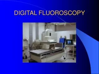
Basic Componets of “NEW DIGITAL” Fluoro“Imaging Chain” Primary Radiation EXIT Radiation Fluoro TUBE PATIENT Analog to Digital Converter ADC Image Intensifier ABC CCD TV
Flat-Panel Detectors (FPD) • II tubes are being replaced by Flat-panel detectors.
Coating for DR • AMORPHOUS SILICON (indirect) • X-ray photon to light photon • AMORPHOUS SELENIUM (direct = trapped e-) • No light