Download
1 / 37
370 likes | 399 Vues
Explore the detailed 3D modelling & simulations of the ALICE Photoinjector Upgrade, showcasing advancements, simulations, and potential enhancements for the injector system. Investigate new components and configurations using innovative technologies.

E N D
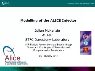
3D Modelling of theALICE Photoinjector Upgrade Julian McKenzie ASTeC, STFC Daresbury Laboratory, UK
ALICE Overview • Nominal Gun Energy 350 keV • Injector Energy 8.35 MeV • Circulating Beam Energy 35 MeV • RF Frequency 1.3 GHz • Bunch Repetition Rate 81.25 MHz • Nominal Bunch Charge 80 pC • Average Current 6.5 mA (Over the 100 ms Bunch Train)
Current ALICE gun – JLab FEL gun clone • 350kV DC photocathode gun • 80pC bunch charge • 25mm GaAs photocathodes • Activated in-situ
GaAs Photocathodes TM base-plate (Al2O3) RM base-plate (Cu, Si) Both reflection and transmission mode photocathodes under development. A.S. Terekhov et al. Institute of Semiconductor Physics, Novisibirsk
Photocathode Preparation System 500kV power supply Photocathode gun Preparation facility
Photocathode Preparation System 3. Heat Cleaning & Activation Caeseation Chamber 1. Atomic Hydrogen cleaning chamber 2. Hermetically sealed transfer vessel & Photocathode Load-lock Introduction Chamber
Preparation System Placement Gun chamber Superconducting booster module 500kV power supply Photocathode preparation facility
CST model of gun chamber XHV vacuum vessel Ceramic insulator Photocathode Electron beam Cathode support stem Anode plate Cathode ball
Side-loading of photocathodes XHV vacuum vessel Photocathode loading Ceramic insulator Electron beam Cathode stem Anode plate Cathode ball
On-axis field map Current gun = red New gun = green
New gun versus current gun Current gun = red New gun = green Includes 330G solenoid located at 0.25m
Potential Vertical Ceramic Gun Possible back illumination of transmission mode photocathodes Back loading of photocathodes
On-axis field maps Longitudinal electric field, V/m Vertical electric field, V/m
GPT simulations showing effect of vertical field With 330G solenoid Gun only Particle tracking in GPT using 3D field maps extracted from CST
Astra simulations of complete injector Current gun = red New gun = green
Off-axis photocathode investigations Aim to reduce ion back bombardment damage by situating the photocathode off-axis • Considered two options: • Moving the whole cathode ball off-axis • Situating the photocathode off-axis on the cathode ball
Electron trajectories calculated using GPT Includes solenoid: Red = standard gun Green = offset cathode ball Blue = offset photocathode Ion tracking simulations not yet performed
Corrector coil simulations • Vertical and horizontal corrector coils located at same position in beamline as the solenoid • Solenoid adds coupling between x and y Without corrector coils Corrector coils modelled in Radia by Ben Shepherd
Add solenoid (300G) solenoid
Add vertical corrector V-cor solenoid
Add horizontal corrector H-cor V-cor solenoid
Electron trajectories with corrector coils included Includes 300G solenoid located at 0.25m Blue = without corrector coils Red = WITH corrector coils (both vertical and horizontal)
Upgraded Diagnostics Suite • Unit “A”: • H-slit since transverse kick is vertical • (longitudinal phase space) • small aperture • (full 80pC bunch from the photocathode • but only a fraction of it in the machine) • Unit “B” : • as it was before • Unit “C”: • insertable Faraday cup • large aperture • (to cut off the outer imperfect part of the beam ) • Unit “D”: • larger (50mm) YAG • (slits etc proved to be unnecessary on this straight)
Multi-Alkali Photocathodes “…is GaAs the only photocathode we can use in DC photocathode guns?” Proceedings of PAC1995
Summary • Photocathode preparation facility designed and under construction • Options of side-loading photocathodes or changing ceramic insulator from horizontal to vertical • 3D CST electrostatic simulations show maximum field on cathode ball of less than 10 MV/m • Investigation underway of locating photocathode off-axis to reduce ion back-bombardment by performing simulations in GPT with 3D field maps • Gun beamline upgrade proposal with extended diagnostics section • Investigation of multi-alkali photocathodes to begin
Acknowledgments • I would like to thank the following people for their direct contribution to this work: • Boris Militsyn • Yuri Saveliev • And all those involved in the Alice gun upgrade: • Ian Burrows • Ryan Cash • Barry Fell • Lee Jones • Keith Middleman • Alex Terekhov (ISP, Novisibirsk)