Capturing the Requirements
Capturing the Requirements. 中国科学技术大学软件学院 孟宁. 2011年9月. Contents. 4.1 The Requirements Process 4.2 Requirements Elicitation 4.4 Types of Requirements 4.4 Characteristic of Requirements 4.5 Modeling Notations 4.6 Requirements and Specification Languages

Capturing the Requirements
E N D
Presentation Transcript
Capturing the Requirements 中国科学技术大学软件学院 孟宁 2011年9月
Contents 4.1 The Requirements Process 4.2 Requirements Elicitation 4.4 Types of Requirements 4.4 Characteristic of Requirements 4.5 Modeling Notations 4.6 Requirements and Specification Languages 4.7 Prototyping Requirements 4.8 Requirements Documentation 4.9 Validation and Verification 4.10 Measuring Requirements 4.11 Choosing a Specification Technique
Chapter 4 Objectives • Eliciting requirements from the customers • Modeling requirements • Reviewing requirements to ensure their quality • Documenting requirements for use by the design and test teams
4.1 The Requirements Process • A requirement is an expression of desired behavior • A requirement deals with • objects or entities • the state they can be in • functions that are performed to change states or object characteristics • Requirements focus on the customer needs, not on the solution or implementation • designate what behavior, without saying how that behavior will be realized
4.1 The Requirements ProcessSidebar 4.1 Why Are Requirements Important? • Top factors that caused project to fail • Incomplete requirements • Lack of user involvement • Unrealistic expectations • Lack of executive support • Changing requirements and specifications • Lack of planning • System no longer needed • Some part of the requirements process is involved in almost all of these causes • Requirements error can be expensive if not detected early
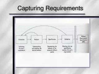
4.1 The Requirements ProcessProcess for Capturing Requirements • Performed by the req. analyst or system analyst • The final outcome is a Software Requirements Specification (SRS) document
4.1 The Requirements ProcessSidebar 4.2 Agile Requirements Modeling • If requirements are tighly coupled and complex, we may be better off with a “heavy” process that empasizes up-front modeling • If the requirements are uncertain, agile methods are an alternative approach • Agile methods gather and implement the requirements in increments • Extreme Programming (XP) is an agile process • The requirements are defined as we build the system • No planning or designing for possible future requirements • Encodes the requirements as test cases that eventually implementation must pass
4.2 Requirements Elicitation • Customers do not always undertand what their needs and problems are • It is important to discuss the requirements with everyone who has a stake in the system • Come up with agreement on what the requirements are • If we can not agree on what the requirements are, then the project is doomed to fail
4.2 Requirements ElicitationStakeholders • Clients: pay for the software to be developed • Customers: buy the software after it is developed • Users: use the system • Domain experts: familiar with the problem that the software must automate • Market Researchers: conduct surveys to determine future trends and potential customers • Lawyers or auditors: familiar with government, safety, or legal requirements • Software engineers or other technology experts
4.2 Requirements ElicitationSidebar 4.3 Using Viewpoints to Manage Inconsistency • No need to resolve inconsitencies early in the requirements process (Easterbrook and Nuseibah, 1996) • Stakeholders' views documented and maintained as separate Viewpoints through the software development process • The requirements analyst defines consistency rules that should apply between Viewpoints • The Viewpoints are analyzed to see if they conform to the consistency requirements • Inconsistencies are highlighted but not adressed until there is sufficient information to make informed decision
4.2 Requirements ElicitationMeans of Eliciting Requirements • Interviewing stake holders • Reviewing available documentations • Observing the current system (if one exists) • Apprenticing with users to learn about user's task in more details • Interviewing user or stakeholders in groups • Using domain specific strategies, such as Joint Application Design, or PIECES • Brainstorming with current and potential users
The Volere requirements process model suggests some additional sources for requirements 4.2 Requirements ElicitationMeans of Eliciting Requirements (continued)
4.3 Types of Requirements • Functional requirement: describes required behavior in terms of required activities • Quality requirement or nonfunctional requirement: describes some quality characteristic that the software must posses • Design constraint: a design decision such as choice of platform or interface components • Process constraint: a restriction on the techniques or resources that can be used to build the system
4.3 Types of RequirementsSidebar 4.4 Making Requirements Testable • Fit criteria form objective standards for judging whether a proposed solution satisfies the requirements • It is easy to set fit criteria for quantifyable requirements • It is hard for subjective quality requirements • Three ways to help make requirements testable • Specify a quantitave description for each adverb and adjective • Replace pronouns with specific names of entities • Make sure that every noun is defined in exaclty one place in the requirements documents
4.3 Types of RequirementsResolving Conflicts • Different stakeholder has different set of requirements • potential conflicting ideas • Need to prioritize requirements • Prioritization might separate requirements into three categories • essential: absolutely must be met • desirable: highly desirable but not necessary • optional: possible but could be eliminated
4.3 Types of RequirementsTwo Kinds of Requirements Documents • Requirements definition: a complete listing of everything the customer wants to achieve • Describing the entities in the environment where the system will be installed • Requirements specification: restates the requirements as a specification of how the proposed system shall behave
Requirements defined anywhwere within the environment's domain, including the system's interface Specification restricted only to the intersection between environment and system domain 4.3 Types of RequirementsTwo Kinds of Requirements Documents (continued)
4.4 Characteristics of Requirements • Correct • Consistent • Unambigious无二义性 • Complete • Feasible • Relevant无与主要目标不相关的需求 • Testable • Traceable
4.5 Modeling Notations • It is important to have standard notations for modeling, documenting, and communicating decisions • Modeling helps us to understand requirements thoroughly • Holes in the models reveal unknown or ambiguous behavior • Multiple, conflicting outputs to the same input reveal inconsistencies in the requirements
4.5 Modeling NotationsEntity-Relationship Diagrams • A popular graphical notational paradigm for representing conceptual models • Has three core constructs • An entity: depicted as a rectangle, represents a collection of real-world objects that have common properties and behaviors • A relationship: depicted as an edge between two entities, with diamond in the middle of the edge specifying the type of relationship • An attribute: an annotation on an entity that describes data or properties associated with the entity
Entity diagram of turnstile problem 4.5 Modeling NotationsEntity-Relationship Diagrams (continued)
4.5 Modeling NotationsEntity-Relationship Diagrams (continued) • ER diagrams are popular because • they provide an overview of the problem to be addressed • the view is relatively stable when changes are made to the problem's requirements • ER diagram is likely to be used to model a problem early in the requirements process
4.5 Modeling NotationsER Diagrams Example: UML Class Diagram • UML (Unified Modeling Language) is a collection of notations used to document software specifications and designs • It represents a system in terms of • objects: akin to entities, organized in classes that have an inheritance hierarchy • methods: actions on the object's variables • The class diagram is the flagship model in any UML specification • A sophisticated ER diagram relating the classes (entities) in the specification
4.5 Modeling NotationsUML Class Diagram (continued) • Attributes and operations are associated with the class rather than instances of the class • A class-scope attribute represented as an underlined attribute, is a data value that is shared by all instances of the class • A class-scope operation written as underlined operation, is an operation performed by the abstract class rather than by class instances • An association, marked as a line between two classes, indicates a relationship between classes' entities
4.5 Modeling NotationsUML Class Diagram (continued) • Aggregate association is an association that represents interaction, or events that involve objects in the associated (marked with white diamond) • “has-a” relationship • Composition association is a special type of aggregation, in which instances of the compound class are physically constructed from instances of component classes (marked with black diamond)
4.5 Modeling NotationsEvent Traces • A graphical description of a sequence of events that are exchanged between real-world entities • Vertical line: the timeline of distinct entity, whose name appear at the top of the line • Horizontal line: an event or interaction between the two entities bounding the line • Time progresses from top to bottom • Each graph depicts a single trace, representing one of several possible behaviors • Traces have a semantic that is relatively precise, simple and easy to understand
Graphical representation of two traces for the turnstile problem trace on the left represents typical behavior trace on the right shows exceptional behavior 4.5 Modeling NotationsEvent Traces (continued)
4.5 Modeling NotationsEvent Traces Exampe: Message Sequence Chart • An enhanced event-trace notation, with facilities for creating and destroying entities, specifiying actions and timers, and composing traces • Vertical line represents a participating entity • A message is depicted as an arrow from the sending entity to the receiving entity • Actions are specified as labeled rectangles positioned on an entity's execution line • Conditions are important states in an entity's evolution, represented as labeled hexagon
Message sequence chart for library loan transaction 4.5 Modeling NotationsMessage Sequence Chart (continued)
4.5 Modeling NotationsState Machines • A graphical description of all dialog between the system and its environment • Node (state) represents a stable set of conditions that exists between event occurences • Edge (transition) represents a change in behavior or condition due to the occurrence of an event • Useful both for specifying dynamic behavior and for describing how behavior should change in response to the history of events that have already occurred
Finite state machine model of the tunstile problem 4.5 Modeling NotationsState Machines (continued)
4.5 Modeling NotationsState Machines (continued) • A path: starting from the machine's initial state and following transitions from state to state • A trace of observable events in the environment • Deterministic state machine: for every state and event there is a unique response
4.5 Modeling NotationsState Machines Example: UML Statechart Diagrams • A UML statechart diagram depicts the dynamic behavior of the objects in a UML class • UML class diagram has no information about how the entities behave, how the behaviors change • A UML model is a collection of concurrently executing statecharts • UML statechart diagram have a rich syntax, including state hierarchy, concurrency, and intermachine coomunication
4.5 Modeling NotationsUML Statechart Diagrams (continued) • State hierarchy is used to unclutter diagrams by collecting into superstate those states with common transitions • A superstate can actually comprise multiple concurrent submachines, separated by dashed line • The submachines are said to operate concurrently
The UML statechart diagram for the Publication class from the Library class model 4.5 Modeling NotationsUML Statechart Diagrams (continued)
An equivalent statechart for Publication class that does not make use of state hierarchy or concurrency comparatively messy and and repetitive 4.5 Modeling NotationsUML Statechart Diagrams (continued)
The UML statechart diagram for Loan association class illustrates how states can be annotated with local variables, actions and activities 4.5 Modeling NotationsUML Statechart Diagrams (continued)
4.5 Modeling NotationsState Machines: Ways of Thinking about State • Equivalence classes of possible future behavior • Periods of time between consecutive event • Named control points in an object's evolution • Partition of an object's behavior
A high-level data-flow diagram for the library problem 4.5 Modeling NotationsData-Flow Diagrams (continued)
4.5 Modeling NotationsData-Flow Diagrams (continued) • Advantage: • Provides an intuitive model of a proposed system's high-level functionality and of the data dependencies among various processes • Disadvantage: • Can be aggravatingly ambiguous to a software developer who is less familiar with the problem being modeled
4.5 Modeling NotationsData-Flow Diagrams Example: Use Cases • Components • A large box: system boundary • Stick figures outside the box: actors, both human and systems • Each oval inside the box: a use case that represents some major required functionality and its variant • A line between an actor and use case: the actor participates in the use case • Use cases do not model all the tasks, instead they are used to specify user views of essential system behavior
Library use cases including borrowing a book, returning a borrowed book, and paying a library fine 4.5 Modeling NotationsUse Cases (continued)
4.5 Modeling NotationsFunctions and Relations • Formal methods or approach: mathematically based specification and design techniques • Formal methods model requirements or software behavior as a collection of mathematical functions or relations • Functions specify the state of the system's execution, and output • A relation is used whenever an input value maps more than one ouput value • Functional method is consistent and complete
Example: representing turnstile problem using two functions One function to keep track of the state One function to specify the turnstile output 4.5 Modeling NotationsFunctions and Relations (continued)
4.5 Modeling NotationsFunctions and Relations Example: Decision Tables • It is a tabular representation of a functional specification that maps events and conditions to appropriate reponses or action • The specification is formal because the inputs (events and conditions) and outputs (actions) may be expressed in natural language • If there is n input conditions, there are 2n possible combination of input conditions • Combinations map to the same set of result can be combined into a single column
Decision table for library functions borrow,return, reserve, and unreserve 4.5 Modeling NotationsDecision Tables (continued)
4.6 Requirements and Specification LanguagesUnified Modeling Language (UML) • Combines multiple notation paradigms • Eight graphical modeling notations, and the OCL constrain language, including • Use-case diagram (a high-level DFD) • Class diagram (an ER diagram) • Sequence diagram (an event trace) • Collaboration diagram (an event trace) • Statechart diagram (a state-machine model) • OCL properties (logic)
4.7 Prototyping RequirementsBuilding a Prototype • To elicit the details of proposed system • To solicit feedback from potential users about • what aspects they would like to see improve • which features are not so useful • what functionality is missing • Determine whether the customer's problem has a feasible solution • Assist in exploring options for otimizing quality requirements