Download
1 / 48
490 likes | 603 Vues
Explore the causes of amplifier stability issues including poles, Bode plots, phase margins, and loop gain models. Learn how to determine if a system has too much delay and ensure good phase margin for stability. Discover methods for stabilizing unity gain circuits with capacitive loads.

E N D
Poles and Bode Plots • Pole Location = fP • Magnitude = -20dB/Decade Slope • Slope begins at fP and continues down as frequency increases • Actual Function = -3dB down @ fP • Phase= -45°/Decade Slope through fP • Decade Above fP Phase = -84.3° • Decade Below fP Phase = -5.7°
Zeros and Bode Plots • Zero Location = fZ • Magnitude = +20dB/Decade Slope • Slope begins at fZ and continues up as frequency increases • Actual Function = +3dB up @ fZ • Phase = +45°/Decade Slope through fZ • Decade Above fZ Phase = +84.3° • Decade Below fZ Phase = 5.7°
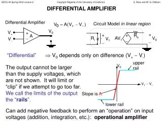
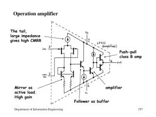
Op-Amp Loop Gain Model VOUT/VIN = Acl = Aol/(1+Aolβ) If Aol >> 1 then Acl ≈ 1/β Aol: Open Loop Gain β: Feedback Factor Acl: Closed Loop Gain
Amplifier Stability Criteria VOUT/VIN = Aol / (1+ Aolβ) If: Aolβ = -1 Then: VOUT/VIN = Aol / 0 ∞ If VOUT/VIN = ∞ Unbounded Gain Any small changes in VIN will result in large changes in VOUT which will feed back to VIN and result in even larger changes in VOUT OSCILLATIONS INSTABILITY !! Aolβ: Loop Gain Aolβ = -1 Phase shift of +180°, Magnitude of 1 (0dB) fcl: frequency where Aolβ = 1 (0dB) Stability Criteria: At fcl, where Aolβ = 1 (0dB), Phase Shift < +180° Desired Phase Margin (distance from +180° Phase Shift) > 45°
Fundamental Cause of Amplifier Stability Issues • Too much delay in the feedback network
Cause of Amplifier Stability Issues • Example circuit with too much delay in the feedback network
Cause of Amplifier Stability Issues • Real circuit translation of too much delay in the feedback network
Cause of Amplifier Stability Issues • Same results as the example circuit
Phase Margin • Phase Margin is a measure of the “delay” in the loop Open-Loop
Small-Signal Overshoot vs. Phase Margin From: Dorf, Richard C. Modern Control Systems. Addison-Wesley Publishing Company. Reading, Massachusetts. Third Edition, 1981.
Damping Ratio vs. Phase Margin From: Dorf, Richard C. Modern Control Systems. Addison-Wesley Publishing Company. Reading, Massachusetts. Third Edition, 1981.
AC Peaking vs. Damping Ratio From: Dorf, Richard C. Modern Control Systems. Addison-Wesley Publishing Company. Reading, Massachusetts. Third Edition, 1981.
Rate of Closure Rate of Closure: Rate at which 1/Beta and AOL intersect ROC = Slope(1/Beta) – Slope(AOL) ROC = 0dB/decade – (-20dB/decade) = 20dB/decade
Rate of Closure and Phase Margin So a pole in AOL or a zero in 1/Beta inside the loop will decrease AOL*B Phase!!
Rate of Closure and Phase Margin Relationship between the AOL and 1/Beta rate of closure and Loop-Gain (AOL*B) phase margin
Rate of Closure and Phase Margin AOL Pole 1/Beta Zero
Testing for Rate of Closure in SPICE • Break the feedback loop and inject a small AC signal Short out the input source Break the loop with L1 at the inverting input Inject an AC stimulus through C1
Breaking the Loop AC DC
Plotting AOL, 1/Beta, and Loop Gain AOL = Vo/Vin 1/Beta = Vo/Vfb AOL*B = Vfb/Vin
Noise Gain • Understanding Noise Gain vs. Signal Gain Inverting Gain, G = -1 Non-Inverting Gain, G = 2 NG = 1 + ΙGΙ = 2 NG = G = 2 Both circuits have a NOISE GAIN (NG) of 2.
Noise Gain • Noise Gain vs. Signal Gain Gain of -0.1V/V, Is it Stable? Noise Gain, NG = 1.1 Inverting Gain, G = -0.1 If it’s unity-gain stable then it’s stable as an inverting attenuator!!!
Capacitive Loads Unity Gain Buffer Circuits Circuits with Gain
Capacitive Loads – Unity Gain Buffers - Results Determine the issue: Pole in AOL!! ROC = 40dB/decade!! Phase Margin 0!! NG = 1V/V = 0dB
Capacitive Loads – Unity Gain Buffers - Theory AOL Load AOL X = Loaded AOL
Stability Options Unity-Gain circuits can only be stabilized by modifying the AOL load
Method 1: Riso - Results Theory: Adds a zero to the Loaded AOL response to cancel the pole
Method 1: Riso - Results When to use: Works well when DC accuracy is not important, or when loads are very light
Method 1: Riso - Design Ensure Good Phase Margin: 1.) Find: fcl and f(AOL = 20dB) 2.) Set Riso to create AOL zero: Good: f(zero) = Fcl for PM ≈ 45 degrees. Better: f(zero) = F(AOL = 20dB) will yield slightly less than 90 degrees phase margin fcl = 222.74kHz f(AOL = 20dB) = 70.41kHz
Method 1: Riso - Design Ensure Good Phase Margin: Test fcl = 222.74kHz →Riso = 0.715Ohms f(AOL = 20dB) = 70.41kHz → Riso = 2.26Ohms
Method 1: Riso - Design Prevent Phase Dip: Place the zero less than 1 decade from the pole, no more than 1.5 decades away Marginal: 1.5 Decades: F(zero) ≤ 35*F(pole) → Riso ≥ Ro/34 →70° Phase ShiftDesirable: 1 Decade: F(zero) ≤ 10*F(pole) → Riso ≥ Ro/9 → 55° Phase Shift
Method 1: Riso – Design Summary Summary: Ensure stability by placing Fzero ≤ 10* Fpole
Method 1: Riso - Disadvantage Disadvantage: Voltage drop across Riso may not be acceptable
Method 2: Riso + Dual Feedback Theory: Features a low-frequency feedback, Rf, to cancel the Riso drop and a high-frequency feedback, Cf, to create the AOL pole and zero.
Method 2: Riso + Dual Feedback When to Use: Only practical solution for very large capacitive loads ≥ 10uF When DC accuracy must be preserved across different current loads