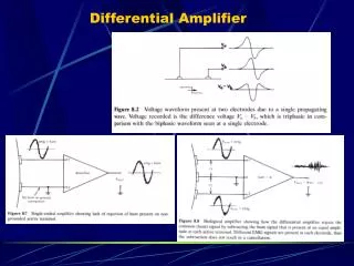
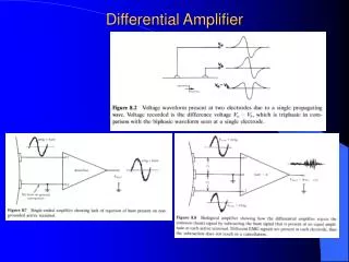
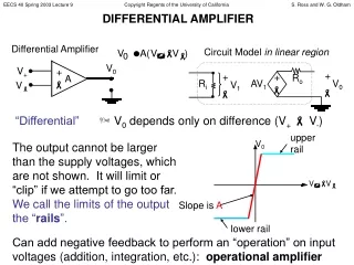
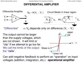
DIFFERENTIAL AMPLIFIER
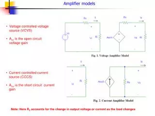
V 0. upper rail. Differential Amplifier. V 0. V +. +. A. Slope is A. . V . +. . lower rail. +. +. V 0. V 1. Circuit Model in linear region. . . R o. R i. AV 1. DIFFERENTIAL AMPLIFIER. “Differential” V 0 depends only on difference (V + V - ) .

DIFFERENTIAL AMPLIFIER
E N D
Presentation Transcript
V0 upper rail Differential Amplifier V0 V+ + A Slope is A V + lower rail + + V0 V1 Circuit Model in linear region Ro Ri AV1 DIFFERENTIAL AMPLIFIER “Differential” V0 depends only on difference (V+ V-) The output cannot be larger than the supply voltages, which are not shown. It will limit or “clip” if we attempt to go too far. We call the limits of the output the “rails”. Can add negative feedback to perform an “operation” on input voltages (addition, integration, etc.): operational amplifier
V0 VIN + + - V1 V0 + + AMPLIFIER ANALYSIS USING CIRCUIT MODEL To analyze an amplifier circuit, you can replace the amplifier with the circuit model, then make sure the output is within “rails”. Example: Voltage Follower Circuit Model in linear region Ro Ri AV1 VIN
ANALYZING OPERATIONAL AMPLIFIER CIRCUITS:“IDEAL” ASSUMPTIONS For easier, approximate analysis of op-amp circuits: Rule 1: Assume A = ∞ Since Vo finite (limited by rails), Vp-Vn = 0 Rule 2: Assume Ri = ∞ No current flows into or out of input (+ and -) terminals Rule 3: Assume Ro = 0 W But current can come out of/into amplifier output!
V0 VIN + OPERATIONAL AMPLIFIER:HOW DOES IT DO THAT? Remember: current can flow out of/into op-amp output How? Op-amp is actually connected to positive and negative voltage supplies which set rails and deliver power to output load (via this output current) Utility of Voltage-Follower: If input voltage source cannot provide much power (current), use voltage follower at output to drive a high power load
ANALYZING AN OP-AMP: TIPS Step 1: KVL around input loop (involves Vin and op-amp inputs) Use Rule 1: Vp-Vn = 0 Step 2: Find the current in the feedback path Use Rule 2: No current into/out of op-amp inputs Step 3: KVL around output loop (involves Vo and feedback path) Remember current can flow in/out op-amp output
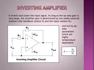
VIN EXAMPLE: INVERTING AMPLIFIER Feedback Path R2 R1 Input Loop V0 + Output Loop
R1 V1 RF R2 V2 V3 V0 R3 + ANOTHER EXAMPLE INVERTING SUMMING AMPLIFIER
IMPORTANT POINTS • The amplifier output voltage does not depend on the “load” (what is attached to the output). • The “form” of the output voltage (the signs of the scaling factors on the input voltages, for example) depends on the amplifier circuit layout. To change the values (magnitudes) of scaling factors, adjust resistor values. • Input voltages which are attached to the + (non-inverting) amplifier terminal get positive scaling factors. Inputs attached to the – (inverting) terminal get negative scaling factors. • You can use these last two principles to design amplifiers which perform a particular function on the input voltages.
R2 R1 Vo V IN NON-INVERTING AMPLIFIER
VIN INTEGRATING AMPLIFIER C R V0 +