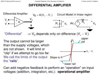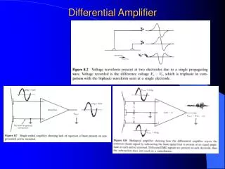
Amplifier models
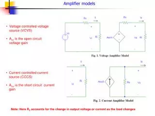
Amplifier models. Voltage controlled voltage source (VCVS) A vo is the open circuit voltage gain. Current controlled current source (CCCS) A isc is the short circuit current gain. Note: Here R 0 accounts for the change in output voltage or current as the load changes.

Amplifier models
E N D
Presentation Transcript
Amplifier models • Voltage controlled voltage source (VCVS) • Avo is the open circuit voltage gain • Current controlled current source (CCCS) • Aisc is the short circuit current gain Note: Here R0 accounts for the change in output voltage or current as the load changes
Conversion from VCVS to CCCS Thus a VCVS can be converted to a CCCS by first finding the current gain Aisc and then putting the series output resistance R0 in case of VCCS parallel to the current source.
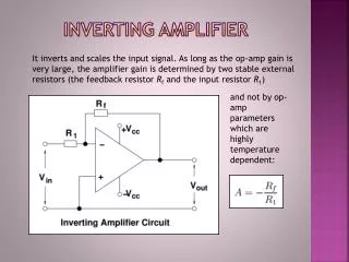
Examples on conversion For a voltage amplifier, if Ri = 1 K, Av0 =100, and R0 = 100 , then draw the equivalent current amplifier circuit. Solution: The current gain Aisc is calculated as Av0Ri/R0 = 1000 The output resistance remains the same but now is in parallel. Input resistance is the same. Thus, the overall circuit looks like shown at the side. Reverse conversion from voltage to current amplifier: Consider a current amplifier of Ri = 1 k, R0 = 20 , and short circuit current gain = 200. Convert into an equivalent voltage amplifier circuit Solution: The voltage gain Avc is calculated as AiscR0/Ri = 4 The output resistance remains the same but now is in series. Input resistance is the same.
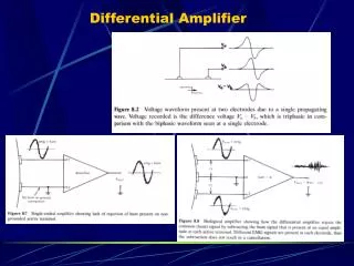
Transconductance and transresistance amplifier models Transconductance amplifier model: Input is voltage, output is current Short circuit transconductance gain Transresistance amplifier model: Input is current, output is voltage
Example Determine the transconductance and transresistance amplifier models for the amplifier shown in the above figure.
Summary of different types of amplifiers So, given the basic voltage amplifier model, you should be able to determine all the other models
Practical applications of different i/p and o/p impedances 1 Variable input impedance of the human body. This happens mainly due to the change in conditions of the skin High input impedance of Electro-cardiograph is necessary The voltage across the ECG machine is: Vs x Ri/(Ri + Rs), which is to be measured. Therefore, the higher the input impedance Ri compared to Rs, the lesser is the variation in input voltage
Practical applications of different i/p and o/p impedances 2 Low input resistance of the ammeter is necessary (so as to not load the circuit, and reduce the current that it is trying to measure). In summary:
Practical example of low o/p impedance of the source Audio amplifiers in various rooms of an office building: If the amplifier feeds several loudspeakers then for different switching conditions, the load will be different for the amplifier, and the sound intensity will be different, which is undesirable. However, if the amplifier output impedance R0 is much less than the (lowest) load resistance, the load voltage is nearly independent of the number of amplifiers turned on or off.
Basic amplifier concepts 1.10 Amplifier Frequency Response • Any periodic signal can be broken down into sinusoidal components by Fourier analysis
Basic amplifier concepts • An amplifier good for a particular frequency range should linearly amplify the signal (containing multiple frequencies) in that range.
Basic amplifier concepts Complex Gain: Q: What is a Phasor? A Phasor is an ac voltage or current that maintains the same phase with respect to a standard reference. Thus, in a circuit the quantities can have a constant phase relationship independent of time.
Basic amplifier concepts │Avmid │ │Avmid │ • AC coupled amplifiers will always have zero gain at dc voltage. Examples include audio amplifiers and ECG amplifiers, where application of dc signal is undesirable. • A DC-coupled amplifier will have a constant gain down to very low frequencies and also dc. Example include amplifiers for video signals.
Basic amplifier concepts The gain of an amplifier reduces at higher frequencies. This is due to the parasitic capacitance and inductances as shown in Fig. 1.38. Stray capacitances occur between the conductor and the ground, while stray inductances happen due to the conductor surrounded by a magnetic field (created by current flow).