Download
1 / 29
540 likes | 2.06k Vues
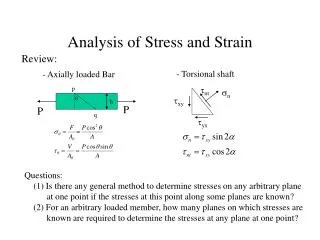
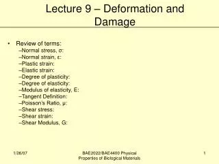
Normal Strain and Stress. Normal Strain and Stress, Stress strain diagram, Hooke’s Law. Strain. When a body is subjected to load, it will deform and can be detected through the changes in length and the changes of angles between them.

E N D
Normal Strain and Stress Normal Strain and Stress, Stress strain diagram, Hooke’s Law
Strain • When a body is subjected to load, it will deform and can be detected through the changes in length and the changes of angles between them. • The deformation is measured through experiment and it is called as strain. • The important of strain: it will be related to stress in the later chapter
Normal Strain Normal strain is detected by the changes in length. e (epsilon) l’: length after deformed l: original length. Note e: • dimensionless • very small (normally is mm (=10-6 m)) • 480(10)-6 m/m = 480 mm/m = 480 “micros” = 0.0480 %
Example 1 When load P is applied, the RIGID lever arm rotates by 0.05o. Calculate the normal strain of wire BD Foundation: DL/L Knowledge required: geometrical equation Rigid: no deformation on the lever
Geometry: The mathematics Sine and Cosine Rule
Example 1 When force P is applied to the rigid lever arm LBD after deformed is DB’ Cosine rule can be applied here Strain:
Example 1 When force P is applied to the rigid lever arm LBD after deformed is DB’ Cosine rule can be applied here Strain:
Example 2 The force applied to the handle of the rigid lever the arm to rotate clockwise through an angle of 3o about pin A. Determine the average normal strain developed in the wire. Originally, the wire is unstretched. Discuss the approach?
Solution LB’D = 0.6155 m e= 0.0258 m/m
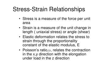
Simple Tensile Test • Strength of a material can only be determined by experiment • The test used by engineers is the tension or compression test • This test is used primarily to determine the relationship between the average normal stress and average normal strain in common engineering materials, such as metals, ceramics, polymers and composites
Conventional Stress–Strain Diagram • Nominal or engineering stress is obtained by dividing the applied load P by the specimen’s original cross-sectional area. • Nominal or engineering strain is obtained by dividing the change in the specimen’s gauge length by the specimen’s original gauge length.
Conventional Stress–Strain Diagram Elastic Behaviour • A straight line • Stress is proportional to strain, i.e., linearly elastic • Upper stress limit, or proportional limit;σpl • If load is removed upon reaching elastic limit, specimen will return to its original shape Yielding • Material deforms permanently; yielding; plastic deformation • Yield stress, σY • Once yield point reached, specimen continues to elongate (strain) without any increase in load • Note figure not drawn to scale, otherwise induced strains is 10-40 times larger than in elastic limit • Material is referred to as being perfectly plastic
Conventional Stress–Strain Diagram • Strain Hardening. • Ultimate stress,σu • While specimen is elongating, its x-sectional area will decrease • Decrease in area is fairly uniform over entire gauge length • Necking • At ultimate stress, cross-sectional area begins to decrease in a localized region of the specimen. • Specimen breaks at the fracture stress.
Stress–Strain Behavior of Ductile and Brittle Materials Ductile Materials • Material that can subjected to large strains before it ruptures is called a ductile material. Brittle Materials • Materials that exhibit little or no yielding before failure are referred to as brittle materials.
Stress–Strain Behavior of Ductile and Brittle Materials Yield Strength • 0.02% strain for ductile material Strain hardening • When ductile material is loaded into the plastic region and then unloaded, elastic strain is recovered. • The plastic strain remains and material is subjected to a permanent set.
Hooke’s Law • Hooke’s Law defines the linear relationship between stress and strain within the elastic region. • E can be used only if a material has linear–elastic behaviour. σ = stress E = modulus of elasticity or Young’s modulus ε = strain E can be derived from stress and strain graph. What is it?
Strain Energy • When material is deformed by external loading, it will store energy internally throughout its volume. • Energy is related to the strains called strain energy. Modulus of Resilience • When stress reaches the proportional limit, the strain-energy density is the modulus of resilience, ur:
Example • The stress–strain diagram for an aluminum alloy that is used for making aircraft parts is shown. When material is stressed to 600 MPa, find the permanent strain that remains in the specimen when load is released. Also, compute the modulus of resilience both before and after the load application. • Approach to the problem: • Parallel to elastic line • Both slope is equal • Distance CD can be calculated based on the slope • Permanent strain: 0.023 – distance CD
Solution • When the specimen is subjected to the load, the strain is approximately 0.023 mm/mm. • The slope of line OA is the modulus of elasticity, • From triangle CBD,
Solution: This strain represents the amount of recovered elastic strain. The permanent strain is Computing the modulus of resilience, Note that the SI system of units is measured in joules, where 1 J = 1 Nm
Modulus of Toughness • Modulus of toughness, ut, represents the entire area under the stress–strain diagram. • It indicates the strain-energy density of the material just before it fractures.
Example The bar DA is rigid and is originally held in the horizontal position when the weight W is supported from C. If the weight causes B to be displaced downward 0.625mm, determine the strain in wires DE and BC. Also if the wires are made of A-36 steel and have a cross-sectional area of 1.25 mm2, determine the weight W. Discuss the approach????
1) Calculate the displacement of D. 2) Based on displacement on D, calculate the strain and normal stress * strain in mm/mm, stress and E in MPa, F in N and length in mm
3) Based on normal stress at wire DE, calculate the T of wire D 4) Calculate W, based on FBD of bar DA 5) Calculate normal stress of wire CB and strain of wire CB Strain can not be calculated as normal stress goes beyond yield stress (Sy = 250 MPa), elastic property is no more applied. Therefore it requires the stress and strain curve to predict the strain
Poisson’s Ratio • n (nu), states that in the elastic range, the ratio of these strains is a constant since the deformations are proportional. • Negative sign since longitudinal elongation (positive strain) causes lateral contraction (negative strain), and vice versa. Poisson’s ratio is dimensionless. Typical values are 1/3 or 1/4.
Example A bar made of A-36 steel has the dimensions shown. If an axial force of P is applied to the bar, determine the change in its length and the change in the dimensions of its cross section after applying the load. The material behaves elastically.
Discuss the approach Approach: Property A-36: E , n 1. s= P/A 2. ez= s / E 3. DLz = L * ez 4. ex = ey = -n ez 5. DLx = L * ex DLy = L * ey
Solution 1) The normal stress in the bar : 4) The contraction strains in both the x and y directions are 2) From the table for A-36 steel, Est = 200 GPa 5) The changes in the dimensions of the cross section are 3) The axial elongation of the bar is therefore