Metamorphic Phase Diagrams
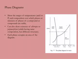
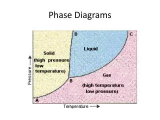
Metamorphic Phase Diagrams. Differ from Igneous Phase Diagrams Show a snapshot of all compositions at given T,P Rock remains at same point but diagram changes. Phase Diagram for Water. The Phase Rule (Gibbs, 1928). Phases (Distinct Materials or States) +


Metamorphic Phase Diagrams
E N D
Presentation Transcript
Metamorphic Phase Diagrams Differ from Igneous Phase Diagrams Show a snapshot of all compositions at given T,P Rock remains at same point but diagram changes
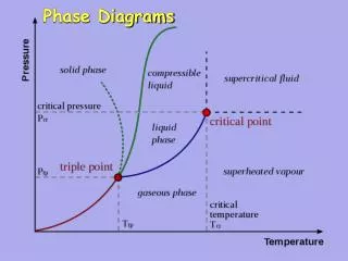
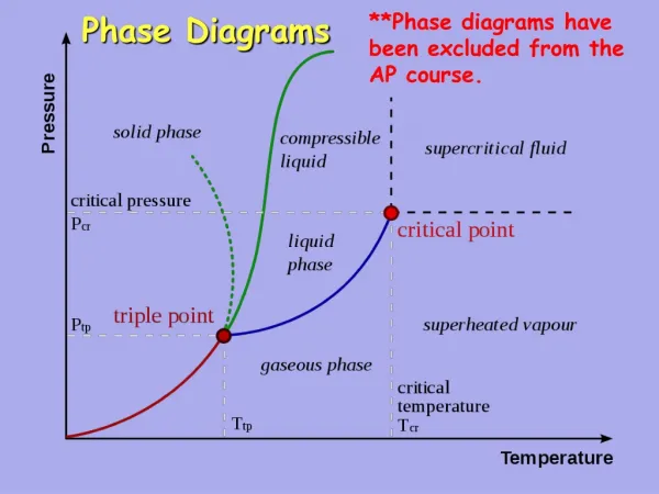
The Phase Rule (Gibbs, 1928) Phases (Distinct Materials or States) + Degrees of Freedom (Independent Variables) = Components + 2
Degrees of Freedom • Pressure • Temperature • PH2O • PCO2 • pH • Oxygen fugacity • Eh
Simplifying Degrees of Freedom • Generally ignore pH, Eh, Oxygen fugacity for most rocks • Important for sulfide systems • Usually care about T,P • Assume PH2O = Ptotal for silicates, PCO2 = 0 • Assume PCO2 = Ptotal for carbonates, PH2O = 0 • Assume PH2O = 0 and PCO2 = 0 in some cases
Simplifying Degrees of Freedom • P + F = C + 2 • If F = 2, then P = C • Number of phases = number of components • Components = SiO2, Al2O3, Fe2O3, FeO, CaO, MgO, Na2O, K2O, TiO2, Cr2O3, MnO, BaO, SrO, P2O5, H2O, CO2, F, Cl
Simplifying Components • We can plot a maximum of three components using triangle diagrams • Ignore SiO2(excess), H2O (excess or 0), CO2 (excess or 0) • Assume P2O5 goes into apatite, Na2O into albite, TiO2 into rutile or ilmenite, Cr2O3, into chromite, F into fluorite or apatite, Cl into halite • Include MnO with FeO, BaO and SrO with CaO, Fe2O3 with Al2O3 or FeO, Cl, F with OH • Subtract major elements as necessary
Simplifying Components • Components reduced to Al2O3, FeO, CaO, MgO, K2O • ACF graphs Al2O3, CaO, (FeO+ MgO) • A’KF graphs Al2O3, (FeO + MgO), K2O • AFM graphs Al2O3, FeO, MgO, K2O in a tetrahedron • SiO2 – CaO – MgO used for carbonate systems • Plot Molar amounts, not weights
Metamorphic Phase Diagrams • Tie lines denote two coexisting phases • Triangular subfields denote three coexisting phases • Phase Diagram is snapshot of mineral combinations under given T,P conditions • Evolution tracked by changes in diagrams • Not really interested in amounts
Metamorphic Phase Diagrams • Normally F = 2, C = 3, P = 3 • On a reaction curve, F = 1, P = 4 • How to get 4 Phases Together: • New Phase Appears in Middle of Field • New Phase Appears on Tie Line • Tie Line Breaks and New One Forms • Changes in Metamorphism • New Minerals Appear • Old Minerals Disappear • Compatibilities Shift
450 C: One Tie Line Replaced by Another(Quartz + Dolomite -> Calcite + Talc)
500 C: New Phase in Middle of Field(Quartz + Talc + Calcite -> Tremolite)
ACF Diagram • Probably most versatile and instructive diagram • A = (Al2O3 + Fe2O3) – (Na2O, + K2O) • Subtract Al2O3 in K-spar and albite • C = CaO - 3.3 * P2O5 • Subtract Ca in apatite • F = FeO + MgO + MnO
A’KF Diagram • A’ = (Al2O3 + Fe2O3) – (Na2O, + K2O) – variable Ca (epidote, garnet, anorthite) • K = K2O • F = FeO + MgO + MnO – amount in diopside or hornblende • Distinguishes K-feldspar and micas
AFM Diagram • Graphs Al2O3, FeO, MgO, K2O • Cross-section through a tetrahedron • Used where MgO and FeO don’t fully substitute • Must include K2O because of micas • A = (Al2O3-3K2O)/(Al2O3-3K2O+FeO+MgO) • M = MgO/ (FeO + MgO) • F = FeO/ (FeO + MgO)