LAN Design: Goals, Considerations, and Switch Features
240 likes | 343 Vues
Understand LAN design goals, considerations, systematization steps, and switch features from layers 1-3. Learn server placement, segmentation, and bandwidth allocation strategies.

LAN Design: Goals, Considerations, and Switch Features
E N D
Presentation Transcript
Ch.5 - Switches CCNA 3 version 3.0 Rick Graziani Cabrillo College
Note to instructors • If you have downloaded this presentation from the Cisco Networking Academy Community FTP Center, this may not be my latest version of this PowerPoint. • For the latest PowerPoints for all my CCNA, CCNP, and Wireless classes, please go to my web site: http://www.cabrillo.cc.ca.us/~rgraziani/ • The username is cisco and the password is perlman for all of my materials. • If you have any questions on any of my materials or the curriculum, please feel free to email me at graziani@cabrillo.edu (I really don’t mind helping.) Also, if you run across any typos or errors in my presentations, please let me know. • I will add “(Updated – date)” next to each presentation on my web site that has been updated since these have been uploaded to the FTP center. Thanks! Rick Rick Graziani graziani@cabrillo.edu
Overview • Describe the four major goals of LAN design • List the key considerations in LAN design • Understand the steps in systematic LAN design • Understand the design issues associated with the Layer 1, 2, and 3 LAN structure, or topology • Describe the three-layer design model • Identify the functions of each layer of the three-layer model • List Cisco access layer switches and their features • List Cisco distribution layer switches and their features • List Cisco core layer switches and their features Rick Graziani graziani@cabrillo.edu
LAN Design Goals • Functionality – The network must work. The network must allow users to meet their job requirements. The network must provide user-to-user and user-to-application connectivity with reasonable speed and reliability. • Scalability – The network must be able to grow. The initial design should grow without any major changes to the overall design. • Adaptability – The network must be designed with a vision toward future technologies. The network should include no element that would limit implementation of new technologies as they become available. • Manageability – The network should be designed to facilitate network monitoring and management to ensure ongoing stability of operation. Rick Graziani graziani@cabrillo.edu
LAN design considerations MDF/IDF To maximize available LAN bandwidth and performance: • The function and placement of servers • Collision detection issues • Segmentation issues • Broadcast domain issues Note: This graphic is confused with its location of the MDF and IDF. Not sure what it is trying to show. IDF Rick Graziani graziani@cabrillo.edu
LAN design considerations • Servers can be categorized into two distinct classes: • Enterprise servers • Workgroup servers • An enterprise server supports all the users on the network by offering services, such as e-mail or Domain Name System (DNS) that everyone in an organization would need because it is a centralized function. • A workgroup server supports a specific set of users, offering services such as word processing and file sharing. • Other examples might include applications that are specific to a group of users. Server Placement Rick Graziani graziani@cabrillo.edu
LAN design considerations • Enterprise servers should be placed in the main distribution facility (MDF). • Traffic to the enterprise servers travels only to the MDF and is not transmitted across other networks. (Not necessarily. If you have a “routed core” it will travel across other networks.) Server Placement Rick Graziani graziani@cabrillo.edu
LAN design considerations • Ideally, workgroup servers should be placed in the intermediate distribution facilities (IDFs) closest to the users accessing the applications on these servers. • By placing workgroup servers close to the users, traffic only has to travel the network infrastructure to an IDF, and does not affect other users on that network segment. • Layer 2 LAN switches located in the MDF and IDFs should have 100 Mbps or more allocated to these servers. Server Placement Rick Graziani graziani@cabrillo.edu
Cabrillo College – MDF/IDF Map MDF IDF Rick Graziani graziani@cabrillo.edu
LAN design considerations • Segmentation is the process of splitting a single collision domain into smaller collision domains. • Creating smaller collision domains reduces the number of collisions on a LAN segment, and allows for greater utilization of bandwidth. • Layer 2 devices such as bridges and switches can be used to segment a LAN into smaller collision domains. • A broadcast domain refers to the set of devices that receive a broadcast data frame originating from any device within that set. • Processing the broadcast data will consume the resources and available bandwidth of the host. • Layer 2 devices such as bridges and switches reduce the size of a collision domain but do not reduce the size of the broadcast domain. • Routers reduce the size of the collision domain and the size of the broadcast domain at Layer 3. Rick Graziani graziani@cabrillo.edu
LAN design methodology • Gather requirements and expectations • Analyze requirements and data • Design the Layer 1, 2, and 3 LAN structure, or topology • Document the logical and physical network implementation 2 1 3 4 OSI layer topology map LAN logical map LAN physical map Cut sheets VLAN logical map Layer 3 logical map Addressing maps Rick Graziani graziani@cabrillo.edu
Layer 1 design • One of the most important components to consider when designing a network is the physical cabling. • Design issues at Layer 1 include the type of cabling to be used, typically copper or fiber-optic, and the overall structure of the cabling. Rick Graziani graziani@cabrillo.edu
Layer 1 design • In a simple star topology with only one wiring closet, the MDF includes one or more horizontal cross-connect (HCC) patch panels. • HCC patch cables are used to connect the Layer 1 horizontal cabling with the Layer 2 LAN switch ports. • The uplink port of the LAN switch, depending on the model, is connected to the Ethernet port of the Layer 3 router using a patch cable. At this point, the end host has a complete physical connection to the router port. Rick Graziani graziani@cabrillo.edu
Layer 1 design • By creating multiple wiring closets, multiple catchment areas are created. • The secondary wiring closets are referred to as intermediate distribution facilities (IDFs). • TIA/EIA-568-A standards specify that IDFs should be connected to the MDF by using vertical cabling, also called backbone cabling. • A vertical cross-connect (VCC) is used to interconnect the various IDFs to the central MDF. • Fiber-optic cabling is normally used because the vertical cable lengths are typically longer than the 100-meter limit for Category 5e UTP cable. Rick Graziani graziani@cabrillo.edu
Layer 2 design • Collisions and collision domain size are two factors that negatively affect the performance of a network. • Microsegmentation of the network reduces the size of collision domains and reduces collisions. • Microsegmentation is implemented through the use of bridges and switches. • The goal is to boost performance for a workgroup or a backbone. • Switches can be used with hubs to provide the appropriate level of performance for different users and servers. Rick Graziani graziani@cabrillo.edu
Layer 3 design • Routers can be used to create unique LAN segments and also allow for connectivity to wide-area networks (WANs), such as the Internet. • Layer 3 routing determines traffic flow between unique physical network segments based on Layer 3 addressing. • Routers provide scalability because they serve as firewalls for broadcasts. • They can also provide scalability by dividing networks into subnetworks, or subnets, based on Layer 3 addresses. • VLAN implementation combines Layer 2 switching and Layer 3 routing technologies to limit both collision domains and broadcast domains. • VLANs can also be used to provide security by creating the VLAN groups according to function and by using routers to communicate between VLANs. Rick Graziani graziani@cabrillo.edu
Switched LANs, access layer overview The hierarchical design model includes the following three layers: • The access layer provides users in workgroups access to the network. • The distribution layer provides policy-based connectivity. • The core layer provides optimal transport between sites. • The core layer is often referred to as the backbone. Rick Graziani graziani@cabrillo.edu
Access layer switches • Access layer switches operate at Layer 2 of the OSI model and provide services such as VLAN membership. • The main purpose of an access layer switch is to allow end users into the network. • An access layer switch should provide this functionality with low cost and high port density. • Catalyst 1900 series • Catalyst 2820 series • Catalyst 2950 series • Catalyst 4000 series • Catalyst 5000 series Rick Graziani graziani@cabrillo.edu
Distribution Layer • The purpose of this layer is to provide a boundary definition in which packet manipulation can take place. • Networks are segmented into broadcast domains by this layer. • Policies can be applied and access control lists can filter packets. • The distribution layer also prevents problems from affecting the core layer. • Switches in this layer operate at Layer 2 and Layer 3. • The distribution layer includes several functions such as the following: • Aggregation of the wiring closet connections • Broadcast/multicast domain definition • Virtual LAN (VLAN) routing • Any media transitions that need to occur • Security Rick Graziani graziani@cabrillo.edu
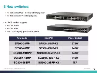
Distribution layer switches 6500 • Distribution layer switches are the aggregation points for multiple access layer switches. • The switch must be able to accommodate the total amount of traffic from the access layer devices. • The distribution layer combines VLAN traffic and is a focal point for policy decisions about traffic flow. • For these reasons distribution layer switches operate at both Layer 2 and Layer 3. • The following Cisco switches are suitable for the distribution layer: • Catalyst 2926G • Catalyst 5000 family • Catalyst 6000 family 2926G Rick Graziani graziani@cabrillo.edu
Core Layer • The core layer is a high-speed switching backbone. • If they do not have an associated router module, an external router is used for the Layer 3 function. • This layer of the network design should not perform any packet manipulation. • Packet manipulation, such as access list filtering, would slow down the switching of packets. • Providing a core infrastructure with redundant alternate paths gives stability to the network in the event of a single device failure. Rick Graziani graziani@cabrillo.edu
Core Layer Switches • In a network design, the core layer can be a routed, or Layer 3, core. • Core layer switches are designed to provide efficient Layer 3 functionality when needed. • Factors such as need, cost, and performance should be considered before a choice is made. • The following Cisco switches are suitable for the core layer: • Catalyst 6500 series • Catalyst 8500 series • IGX 8400 series • Lightstream 1010 Lightstream 1010 8540 Rick Graziani graziani@cabrillo.edu
Summary Rick Graziani graziani@cabrillo.edu
Ch.5 - Switches CCNA 3 version 3.0 Rick Graziani Cabrillo College