Switches
Switches. LAN Design LAN Switches. Workgroup Provide file/print/application services to groups of users Placed in IDF close to users Enterprise Provide enterprise services such as DNS, email, applications Increasing trend to enterprise servers in organisations Should be placed in MDF.

Switches
E N D
Presentation Transcript
Switches LAN Design LAN Switches
Workgroup Provide file/print/application services to groups of users Placed in IDF close to users Enterprise Provide enterprise services such as DNS, email, applications Increasing trend to enterprise servers in organisations Should be placed in MDF LAN Design - Servers
Goal to maximise availability Throughput Response time Access to resources LAN Design - Availability
Copper medium? – CAT5, CAT5e, CAT6 UTP/STP Fibre? Position of MDF/IDF to create appropriate catchment areas Layer 1 Design
Flow control, error detection & correction, reduce congestion Reduce collision domain size & effects of collisions Keep collision domains small – ideally fully switched full-duplex environment Layer 2 Design
Controls traffic flow between network segments Logical addressing scheme to separate different network/workgroup functions Broadcast control Layer 3 Design
Hierarchical Design Model • Core layer – backbone – no packet manipulation • Distribution layer – packet manipulation, interconnecting workgroups, Layer 3 switches, enterprise servers • Access layer – closest to user/workgroup – hosts, switches, workgroup servers
NOTE: The following is Cisco’s logical idea of planning a LAN. Their design is an approach but not the only one. Medium & smaller companies will depend on the ideas of their people to come up with design criteria – this is where the Cisco planning criteria can be used. This chapter will give additional requirements & suggestions for your LAN design.
First step in designing a LAN • establish & document the goals of the design.It is based on: • functionality –design must meet the job requirement – must work; connectivity with reasonable speed & reliability • scalability– initial design should grow without any major chances to overall design • adaptability– design toward the future (Frame Relay over ATM; SMDS, Switched Multi-megabit Data Service, to ATM) • manageability– design to facilitate network monitoring & management • Inter-network design seeks to provide the greatest availability for the least cost.
One needs to consider the following in overall LAN design: • function & placement of servers • collision detection • place devices to reduce the collision • contention refers to excessive collisions on Ethernet caused by too many devices • segmentation • use bridges, switches & routers to separate collision domains • note for bridges & switches; don’t forward collisions, but still belong to the broadcast domain • bandwidth vs. broadcast domains • bandwidth domain is everything associated with one port on a bridge /switch. All workstations within one bandwidth domain compete for the same LAN bandwidth resource.
Under segmentation: bridges & switches are used • results in multiple collision domains • still a single broadcast domain • Bandwidth domain is everything associated with one port on a bridge or switch. • For Ethernet switches, a bandwidth domain is also known as a collision domain.
Cisco’s design methodology: • Gather the users’ requirements & expectations • organization’s history • operational policies • what their business is • who has the authority to make decisions on network changes • 2) Analyze requirements • what are the voice & data requirements; which is in more demand; affects bandwidth • requirements of the users • 3) Design the layer 1,2,3 i.e. topology • type of topology – star, extended star (most common; 802.3) • cabling ( TIA/EIA-568-A); UTP; FIBER • type of cabling determines the distance of the catchment area • 4) Document the logical & physical network implementation
Servers: • Two distinct classes: • enterprise server – • supports all the users on the network by offering services (e-mail, DNS) • placed in the MDF • workgroup server – • applications for users • placed in the IDF
Cisco: between the MDF and IDF, the layer 2 LAN switches should have 100Mbps or more allocated for these servers. Intranet versus the internet is that the public does not have access to the organization intranet. When layer 2 bridges or switches are used for segmentation, they create separate collision domains, and hence increase bandwidth to individual stations. A bandwidth domain is everything associated with one port on a bridge or switch.
MDF – Main Distribution Facility • HCC – Horizontal cross-connect • Wiring closet where the horizontal cabling connects to a patch panel that is connected by backbone cabling to the MDF • IDF – Intermediate Distribution Facility • Used when a second wiring closed is needed because the hosts are outside of the 100 meter limit. Multiple catchment areas are formed. The IDF is connected to the MDF. • IDF is connected to the MDF by using vertical cabling, also called the backbone cabling • VCC – Vertical cross-connect • Is used to interconnect the various IDFs to the central MDF. • Fast Ethernet, cooper wire ( 100Base-TX) & fiber-optic (100Base-FX) is used to connect the MDF to the IDF.
Layer 2 devices, bridges/switches purposes in the network is to provide: • flow control • error detection • error correction • reduce congestion
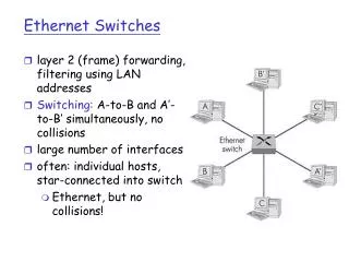
Asymmetric Switching / Symmetric Switching 10 Mbps switch 10 Mbps 10 Mbps 10 Mbps switch 10 Mbps 100 Mbps
In a pure switched LAN environment, the size of the collision domain is two hosts. Routers allows for segmentation of the LAN into unique physical & logical networks.Routers provide scalability because they can serve as firewalls for broadcasts.
3-layer Model Other sites/Internet Core Distribution Campus Backbone Building Backbone Access
3-layer Model Core Other sites/Internet Core • implemented as WAN • doesn’t perform any packet manipulation • no ACLs, nor filtering • were redundant paths are established • load sharing & rapid convergence of routing protocols • efficient use of bandwidth
3-layer Model Distribution Core Campus backbone Distribution Building backbone • demarc between access & core layers • ACLs are added; filtering; packet manipulation • VLAN routing • workgroup access to the core layer • broadcast/multicast domain definition • policy-based connectivity (what is acceptable traffic) • where remote sites have access • security
3-layer Model Access • where local end users have access to network • shared bandwidth • switched bandwidth • MAC-layer filtering • microsegmentation • isolate broadcast traffic from the workgroup • ACLs & filtering • LAN • logical segmentation into functions Access
Server Placement Core Distribution Enterprise Server Access 1 Too much traffic for router 1 when enterprise server placed at access layer.
Server Placement Core Enterprise Server Distribution Access 1 Less traffic for router 1 when enterprise server placed at distribution layer.
Server Placement Workgroup Server 1 Workgroup server is placed at access layer of site where the largest concentration of users are located.
Enterprise servers are placed at the highest layer in the hierarchy. Workgroup servers are placed nearest to the group that is using it.
Cisco suggests the following equipment for physical design: • core (routers) • 12000 7500 7200 7000 • distribution (routers) • 4500 400 3600 • access (routers) • 2600 2500 1700 1600