Download
1 / 17
180 likes | 208 Vues
Explore the innovative pressure pulse technology for gas lift wells, analyzing gas-liquid mass rate and flow conditions with high repeatability. Learn about its applications, from on-demand testing to wellbore flow analysis.

E N D
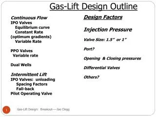
PRESSURE PULSE ANALYSIS OF GAS LIFT WELLS J.S. Gudmundsson, I. Durgut Norwegian University of Science and Technology 7491 Trondheim J. Rønnevig, K. Korsan, H.K. Celius Markland AS 7462 Trondheim 2001 Fall ASME/API Gas Lift Workshop November 12-13, 2001, Aberdeen
Contents of Paper Introduction Pressure Pulse Generation Mass Flow Rate Line Packing Multiphase Mixtures Operational Issues Wells and Pipelines Limited-Installation Test Gas Lift Analysis Concluding Remarks
Pressure Pulse Technology • Gas-Liquid Mass Rate • Flow Condition Analysis • Wells and Flowlines • Field Tested Offshore • On-Demand Testing • Quick-Acting Valve • Pressure Transducers • Patented World-Wide • Licensed to Markland
A B Pressure B B A A LAB Time
Pressure Pulse Mass RateNo Calibration Needed Δp (Pa) = ρ u a a (m/s) = ΔL/ Δt G (kg/s.m2) = ρ u w (kg/s) = G A w (kg/s) = Δp A/a
Pressure Pulse FLOW CONDITION ANALYSIS A quick-acting valve stops the flow. The wellbore pressure drop needed to overcome wall friction during production, becomes available as static pressure at wellhead. This change in pressure propagatescontinuously at the speed of sound back to the wellhead. The resulting pressure-time log can be used in flow condition analysis. In-house rapid pressure transient and speed of sound models and commercial wellbore flow model used (convert to pressure-distance log).
Pressure Pulse Flow Condition AnalysisOil Producer Example 2 4 7 9 6 3 5 10 8 Reflections: 1 = diameter change at 382 m 2 = diameter change above SCSSV 3 = diameter change below SCSSV 4,5,6 = secondary reflections 7 = Bubble point (2300 m) 8 = secondary reflection from bubble point 9 = diameter reduction before inflow zone 10 = bottom hole 1
Pressure Pulse Limited-Installation TestOffshore Well A • Measured depth 4440 m, vertical depth 2270 m • Tubing ID reduced from 4.89” to 3.55” at 650 m depth • Oil gravity 35 API, gas gravity 0.89 • GOR 24.8 Sm3/m3, produced GOR 635 Sm3/m3 • Liquid production rate 1167 Sm3/day, WC 66.8% • WHP 67 bar, BHP 234 bar • WHT 76 C, BHT 100 C • Void fraction at wellhead 0.63
1100 meters 1750 meters 2100 meters
Pressure Pulse Gas Lift AnalysisWell B • Vertical well 3500 m deep • Tubing ID 0.1 m • Gravity oil 32 API, gas 0.85, water 1.103 • GOR 50 Sm3/m3, WC 50% • WHP 50 bara • Liquid production rate 400 Sm3/d • Gas injection rate 100 MSm3/d • Valves 1100 m, 1750 m and 2100 m depth
Pressure Pulse Analysis of Gas Lift WellsCONCLUDING REMARKS • Pressure pulse technology used for gas-liquid mass rate and wellbore flow condition analysis. On-demand testing. • Technology is flexible, robust and gives highly-repeatable results. Limited and extensive-installations tested offshore. • Location of active gas lift valve simulated for typical well using models of rapid transients, sound speed and wellbore flow models. • Pressure pulse technology can be used for a range of applications, including gas lift optimisation (allocation of injection gas).