Download

1 / 30
300 likes | 389 Vues
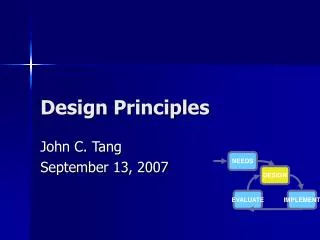
How to design feedback filters? E2E meeting September 27, 2006 Osamu Miyakawa, Caltech. Single Fabry-Perot cavity. Seismic noise. Error signal. Seismic noise. Suspension. Locking area. Suspension. Plant. Lock point. Coil-magnet Actuator. Pick off. Laser. EOM. Signal[a.u.]. ITM.

E N D
How to design feedback filters? E2E meeting September 27, 2006 Osamu Miyakawa, Caltech E2E meeting, September 2006
Single Fabry-Perot cavity Seismic noise Error signal Seismic noise Suspension Locking area Suspension Plant Lock point Coil-magnet Actuator Pick off Laser EOM Signal[a.u.] ITM Actuator ETM Photo detector L Feedback filter 16Hz:LIGO 1.6kHz:40m Oscillator Mixer Sensor Feedback filter P: cavity pole S: flat F: ?? A: suspension TF f -1 P S Noise Plant Sensor A ~1Hz Actuator F f -2 Feedback filter E2E meeting, September 2006
Condition for stable control P S Noise Plant Sensor A Actuator F Feedback filter 1. Phase delay of OLTF at UGF (unity gain frequency) must be less than 180 degree. 2. Enough gain at DC to suppress outloop noise into linear range. E2E meeting, September 2006
Transfer function fromNoise N to signal Vout P S Noise Plant Sensor A Actuator F Feedback filter E2E meeting, September 2006
P S Noise Plant Sensor A Actuator F Feedback filter Transfer function fromoutloop noise to inloop noise Outloop noise N is suppressed by OLG G to inloop noise N/(1+G), then it is multiplied by TF in loop. E2E meeting, September 2006
2pole: 180deg delay 1000 f -2 100 Gain 10 1 180 90 Phase [deg] 0 -90 -180 100 1000 1 10 Frequency log f [Hz] Basic concept :relationship between gain and phase 1pole: 90deg delay 1000 f -1 100 Gain 10 1 180 90 Phase [deg] 0 -90 -180 100 1000 1 10 Frequency log f [Hz] 1zero: 90deg advance 2zero: 180deg advance 1000 1000 100 100 f +1 f +2 Gain Gain 10 10 1 1 180 180 90 90 Phase [deg] Phase [deg] 0 0 -90 -90 -180 -180 100 1000 100 1000 1 10 1 10 Frequency log f [Hz] Frequency log f [Hz] E2E meeting, September 2006
1kHz 1kHz 1Hz 1Hz f -1 f -1 f -2 f -2 1kHz 10Hz f +1 f -1 zero@10Hz pole@1kHz,1kHz Open loop TF Conditoin 2: Phase delayof OLG at UGF must beless than 180 degree. (UGF: frequency at gain = 1) P : cavity pole x S : flat x F : ?? x A : suspension = system TF 1000000 10000 f -2 100 Gain 1 0.01 f -3 0.001 0.0001 90 0 -90 Phase [deg] Not stable! -180 -270 0.1 1 10 100 1k 10k Frequency log f [Hz] Phase restore P : cavity pole x S : flat x F : x A : suspension = OLTF 1000000 f -2 10000 f -1 100 Gain 1 0.01 f -4 0.001 0.0001 90 0 -90 Phase [deg] -180 -270 0.1 1 10 100 1k 10k Frequency log f [Hz] E2E meeting, September 2006
Example of Feedback filterused in 40m arm cavity Phase restore F : 4kHz 10Hz f +1 f -1 zero@10Hz pole@4kHz,4kHz 85degree Phase advance E2E meeting, September 2006
1kHz 1Hz f -1 f -2 Boost filter Conditoin 2:Enough gain at DCto suppress outloop noise within linear range. Wave length: ~ 10-6m Finesse: ~ 1000 FWHM (full width half maximum): ~10-9m Seismic noise N: ~10-6m @1Hz Q of suspension: ~10 Required gain at 1Hz > 104 FWHM ~ 10-9m Wave length ~ 10-6m Phase Restore + Boost P : cavity pole x S : flat x F : x A : suspension = OLTF 1000000 f -4 f -2 1kHz 10000 f -1 10Hz 100 Gain 1 f +1 f -1 f -4 0.01 0.001 0.0001 zero@10Hz pole@1kHz,1kHz 90 0 -90 Phase [deg] -180 -270 0.1 1 10 100 1k 10k Frequency log f [Hz] E2E meeting, September 2006
How to adjust feedback gain? High gain: limited by phase delay due to cavity pole, circuit, DAC/ADC time delay, etc. Low gain: limited by phase delay of boost, or by too low DC gain. 1000000 f -4 10000 f -1 100 Once you get stable operation, it is very important to measure open loop TF to see how stable! Gain 1 0.01 f -4 0.001 0.0001 90 0 -90 Phase [deg] -180 -270 0.1 1 10 100 1k 10k Frequency log f [Hz] E2E meeting, September 2006
P S Noise Plant Sensor A Actuator F Feedback filter How to measure Open Loop TF? 1. Use closed transfer function: • Measure • Calculate G 2. Measure OLTF directly • Measure E2E meeting, September 2006
Example of measured Open loop TF f -1 slope UGF Generally, phase margin should be more than 30degree at least. Phase margin 45degree E2E meeting, September 2006
P S Noise Plant Sensor A Actuator F Feedback filter Why low frequency measurement is dirty? Excitation signal is suppressed a lot with very high gain G>>1 at low frequency. E2E meeting, September 2006
What is Coherence? • Coherence: coh(f) How much related between input and output • 0 < coh(f) < 1 • Coherence is sometimes convenient to estimate whether the measurement is reliable. • Generally, If coherence is smaller than 0.8 the measurement is not good. E2E meeting, September 2006
1 Gain 0.1 1 10 100 1k 10k Frequency log f [Hz] What does Closed Loop TF mean? P S Noise Plant There are two definitions for closed loop TF Sensor A Actuator F Feedback filter UGF • C1 :used to estimate gain oscillation • Measure • Gain oscillation is caused by small phase margin at UGF. • C2 : • Measure UGF 1 Gain 0.1 1 10 100 1k 10k Frequency log f [Hz] E2E meeting, September 2006
Example of measured Closed loop TF Gain oscillation 6dB Generally, gain oscillation should be less than 10dB at most. E2E meeting, September 2006
Example of measured Closed loop TF E2E meeting, September 2006
How to measure plant TF? P S Noise Plant Sensor A Once system become stable, you can measure given plant TF. Actuator F Feedback filter • Measure: 1000000 10000 f -2 100 Gain 1 0.01 f -3 0.001 0.0001 90 0 -90 Phase [deg] -180 -270 0.1 1 10 100 1k 10k Frequency log f [Hz] E2E meeting, September 2006
Example: actuator x optical plant x sensor f -2 slope E2E meeting, September 2006
Plant Seismic noise Suspension Coil-magnet Actuator Sensor Actuator ETM Feedback filter Feedback filter Q:~1000 f -2 ~1Hz Example: suspension Local damping P: flat S: flat F: ?? A: suspension TF OLTF ~10Hz f +1 zero@0Hz pole@10Hz 1000 UGF 100 P S f -1 10 f +1 Gain Noise 1 Plant Sensor 0.01 f -2 0.001 A 0.0001 90 Actuator Phase margin 90degree 0 F -90 Phase [deg] -180 -270 Feedback filter 100 0.1 1 10 Frequency log f [Hz] E2E meeting, September 2006
M0: pitch Main Ref. Damped DOFs (OSEM DOFs) 6(6) M0 0(3) M1 0(3) M2 0(0) M3 Zero @ 0Hz Pole @ 10,10Hz Example in E2EQuad-suspension: local damping P S Noise Plant Sensor A F Actuator Feedback filter E2E meeting, September 2006
f -2 1000000 10000 f -1 Gain P S 100 1 Plant Sensor 0.01 A1 A2 90 Feedback filter 1 0 -90 Actuator 1 Phase [deg] F1 Actuator 2 -180 -270 F2 0.1 1 10 100 1k 10k Feedback filter 2 Frequency log f [Hz] Advanced example: Double loop • P: cavity pole • S: flat • F1: cavity pole restore • F2: AC couple, 1pole, cavity pole restore • A1: suspension TF • A2: flat • OLTF Seismic noise Seismic noise Suspension Suspension Plant Coil-magnet Actuator Pick off Laser EOM PZT ITM Actuator 1 ETM Actuator 2 ~1Hz Photo detector Feedback filter f -2 Oscillator Mixer Sensor Feedback filter 1 Phase margin at UGF > 0 deg ( >30deg) Relative phase margin at cross over frequency > 0deg ( >30deg) Feedback filter 2 E2E meeting, September 2006
Measured open loop gain of MC Cross over frequency Unity gain frequency Relative phase = 165deg Phase margin=28.4deg E2E meeting, September 2006
Measured cross over frequency of MC Gl VCO loop Gm Mirror loop V2 V1 • Cross over frequency = 26.6Hz • Phase margin = 15degree E2E meeting, September 2006
APPENDIX E2E meeting, September 2006
Fa Fdemod Fb ? Example: MC loop Equation of servo topology TO IFO PSL E2E meeting, September 2006
Approximation of Frequency noiseof MC Transmitted light C A B A B C E2E meeting, September 2006
-Nex(Gl+Gm) ~ -Ne 1+Gl+Gm ~ Ne Ne 1+Gl+Gm 1+Gl+Gm Example:Error signal or Feedback signal? • Residual Frequency noise • In-loop noise • Out-loop noise Fres Ne + + Suppression factor by MC gain, estimated by another measurement <<Ne x EpafEl • Which is better? • Calibration To avoid the electronic noise of feedback filter E2E meeting, September 2006
Example:Calibration with complicated optical response S C DARM_IN1 Cavity response Sensing EXC DARM_IN2 P pendulum Use DARM_IN1 : error signal • Measure DARM_IN2/EXC= • Estimate S • Measure (or estimate) C Use DARM_OUT: feedback signal • Measure DARM_IN1/EXC= • Estimate P Feedback filter F DARM_OUT E2E meeting, September 2006
Coupling between 2 loops 4 5 P: plant,IFO F: feedback filter S: suspension C: coupling constant from l- to L- : shotnoise limited sensitivity of l- G: open loop gain PL- C S L- loop FL- 1 3 Pl- 2 Calibrated noise S l- loop 6 Fl- E2E meeting, September 2006