Mechanical Systems Basics for Engineers
420 likes | 545 Vues
Learn about motion, forces, levers, moments, linkages, free body diagrams, and more in this comprehensive unit covering mechanical systems.

Mechanical Systems Basics for Engineers
E N D
Presentation Transcript
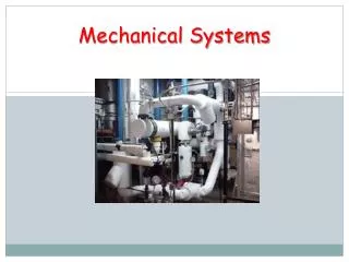
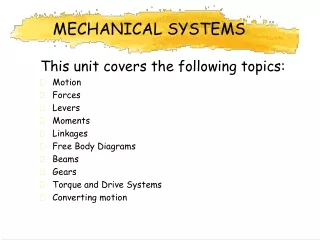
MECHANICAL SYSTEMS This unit covers the following topics: • Motion • Forces • Levers • Moments • Linkages • Free Body Diagrams • Beams • Gears • Torque and Drive Systems • Converting motion
Introduction • Mechanisms are widely used in industry and society • Many mechanisms will be familiar to you
(Intro continued) • Many industrial processes involve electronic control, mechanisms provide the muscle to do the work • All mechanisms involve: • Some kind of motion • Some kind of force • Make a job easier to do • Need an input to make them work • Produce some kind of product
4 Basic Kinds Of Motion Rotary • Turning in a circle • Linear • Moving in a straight line • Reciprocating • Backwards and forwards movement • Oscillating • Swinging back and forwards
Motion Task 1 • Identify the type of motion shown by the following activities. • Complete a systems diagram for each
Motion Task 2 • Consider the tools and machines you have used/ seen in CDT • List up to three tools or machines for each basic type of motion • Rotary • Linear • Reciprocating • Oscillating
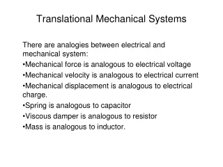
Forces • Force causes acceleration • Force is measured in Newtons (N) • There are several different types of forces that can be applied to bodies and structures
Static Forces • Static forces do not usually cause motion • Consider a tall building • The weight of the material it is built from, and the people and furniture inside it are static loads
Dynamic Loads • Usually causes a movement • The value of the force can be variable • Again consider a tall building • Variable winds add an extra force or load to the structure • The engineer must allow for this
Bending Forces • Structures that carry loads across their length are subject to bending forces • Consider a car driving across a bridge
Shear Forces • These are tearing or cutting forces • Scissors are an example of these
Torsion Forces • Torque is a turning force which tries to twist a structure
Compression Forces • Compression forces try to squash a structure • Consider a column • The weight down is balanced by the reaction from the ground • The forces act to try and shorten the column
Forces in Tension • Tensile forces try to stretch a structure • Consider a crane’s lifting cable • The weight tries to stretch or pull the cable apart • Cables in tension can have small diameters compared to members in compression
LEVERS • In its simplest form, a lever is a stick that is free to pivot or move back and forth at a certain point. • Levers are probably the most common simple machine because just about anything that has a handle on it has a lever attached. • The point on which the lever moves is called the fulcrum. • By changing the position of the fulcrum, you can gain extra power with less effort.
LEVERS • How do you move a heavy person? • If you put the fulcrum in the middle, you won't have a chance. But if you slide the fulcrum closer to the heavy person, it will be easier to lift. • Where's the trade-off? • Well, to get this helping hand, your side of the see-saw is much longer (and higher off the ground), so you have to move it a much greater distance to get the lift
LEVERS • Draw the universal system for a lever • Copy the line diagram of a lever
Basic Types Of Lever • Levers can be either force or distance multipliers (not both)
EFFORT = 260 N LOAD = 750 N 600 mm Force Multiplier Ratio • Consider the lever shown • The LOAD is about 3 times more than the EFFORT • LOAD/EFFORT gives force multiplier ratio
Movement Multiplier Ratio • Something for nothing? • Applying less force to move the load must involve a trade off. • The effort must be moved through a greater distance • In our example the effort moves much more than the load • Movement multiplier ratio = distance moved by effort distance moved by load
Efficiency • The friction and inertia associated with moving an object means that some of the input energy is lost • Since losses occur, the system is not 100% efficient • Efficiency = = Force Ratio x 100 Movement Ratio • Losses in a lever could be friction in the fulcrum, strain in the lever as it bends slightly and maybe sound. • Complete the following tasks:
Task 1 • Draw a universal system diagram for a lever • Complete the following diagram, indicating clearly the LOAD, EFFORT and FULCRUM
Task 2 • Calculate the force- multiplier ratio of the following levers, show all working Load 100N
EFFORT = 150 N LOAD = 450 N 650 mm 200 mm Task 3 • A diagram for a lever system is shown below. • Find the force- multiplier of the lever system • Calculate the movement- multiplier ratio of the lever • Calculate the efficiency of the system • Identify possible efficiency losses in the system
Classes of Levers • Levers can be divided into three distinct types (classes) • Determined by the position of the load, effort and fulcrum. • Class 1 • In class 1 levers the effort is on one side of the fulcrum and the load is on the opposite side. • Class 1 levers are the simplest to understand: the longer the crowbar the easier it is to prise open the lid.
LOAD EFFORT FULCRUM CLASS of LEVER • Class 2 • In class 2 levers the fulcrum is at one end of the lever and the load and the effort are spaced out on the other end of the bar. • The load must be closer to the fulcrum than the effort • A wheelbarrow is a good example of a class 2 lever. The wheel is the fulcrum, the load is in the container area and the effort is applied to the handles.
CLASS of LEVER • Class 3 • Class 3 levers are similar to class 2 levers except that now the effort is closer to the fulcrum than the load • This means that more effort has to be applied to move the load. This type of lever is used when mechanisms require a large output movement for a small input movement.
Task 4 For each of the following tools, state the class of lever
ROPE WEIGHT HINGE P 2 m TURNING EFFECT M O M E N T S • A moment is a turning force • Consider the system shown: • A weight is attached to a metal rod • The rod is free to rotate around a hinge • What happens if the rope is cut? • The weight exerts a moment of 20Nm (Force x Distance)
Lever Systems • The lever shown is in equilibrium (a steady state) • The input force exerts an anticlockwise moment • The output force exerts a clockwise moment • To be in equilibrium both moments must be equal
The Principle of Moments • The sum of the moments must equal zero • CWM = ACWM • Example: Prove that the following system is in equilibrium
Solution • For equilibrium, the CWM = ACWM. • A moment is a force multiplied by a distance • CWM = ACWM • F1¹ d1 = F2 d2 • The load exerts a clockwise moment (tends to make the lever turn clockwise) • Clockwise moment = 200 N 2 m = 400 Nm • The effort exerts a anticlockwise moment. • Anticlockwise moment = 400 N 1 m = 400 Nm • CWM = ACWM • Therefore the lever is in a state of equilibrium.
Task One • A car footbrake uses a lever action to amplify force transmitted by the driver to the braking system when the driver’s foot presses the foot-pedal. If the drivers foot can exert a force of 5000N, what force will be transmitted to the braking system?
Solution • This is a class 2 lever. Take moments about the fulcrum to find the force on the braking system. Notice the distance from the fulcrum to the input is 600 mm. • The input tends to make the lever turn clockwise; the braking system is opposing the input and so acts to turn the lever anticlockwise. • The principle of moments states that: CWM = ACWM F1 d1 = F2 d2 5000 N 0.6 m = braking force 0.1 m braking force = 5000 N 0.6 m 0.1 m braking force = 30,000 N or 30 kN
Questions: • For the system shown: • If the handle length is 250mm and the effort to turn it is 15N, what moment would close the tap valve? • What is the benefit of this type of tap? • Suggest a situation where this type of tap would be useful
Task 2 • Calculate the force- multiplier ratio of the following levers, show all working. Calculate a suitable distance between effort and load to produce equilibrium. Load 600N
EFFORT = 150 N LOAD = 450 N 650 mm 200 mm Task 3 • A diagram for a lever system is shown below. • Find the force- multiplier of the lever system • Calculate the movement- multiplier ratio of the lever • Calculate the efficiency of the system • Identify possible efficiency losses in the system