Intersystem Handoff and Authentication IS-41
Intersystem Handoff and Authentication IS-41. 오재준 Nclab mega5@kw.ac.kr. 6.1 IS-41 Intersystem Handoff. Two BSs are connected to different MSCs Four types of intersystem handoff Handoff-forward Handoff-backward Handoff-to-third Path minimization.

Intersystem Handoff and Authentication IS-41
E N D
Presentation Transcript
Intersystem Handoff and Authentication IS-41 오재준 Nclab mega5@kw.ac.kr
6.1 IS-41 Intersystem Handoff • Two BSs are connected to different MSCs • Four types of intersystem handoff • Handoff-forward • Handoff-backward • Handoff-to-third • Path minimization
6.1.1 Handoff Measurement • Step1 • - HandoffMeasurementRequest • - set 7 second LMMRT • Step2 • - Performs signal measurement • - HandoffMeasurementRequest LMMR (location measurement maximum response timer)
6.1.2 Handoff-Forward(1) • InterSwitchCount parameter , MAXHANDOFF • Step 1 • - MSC A initiates the h/o-forward procedure • - allocate the trunk • - sends a query msg FacilitiesDirective (INVOKE) • - set 12 second HOT (handoff order timer) • - expired : release trunk • FacilitiesReleases with “HandoffAbort not received” • 4-15 CTT set -> FacilitiesReleases • Step 2 • - check if the voice channel is avaible • Step 2.1 (no radio channel is available) • - FacilitiesDirective (RETURN ERROR) with “Resource Shortage” • - stop HOT • - exchange FacilitiesReleases msg. • - MSCs exit the task
6.1.2 Handoff-Forward (2) • Step2 • Step2.2 (radio channel is available) • - FacilitiesDirective (RETURN RESULT) with selected channel number. • - excute step3, step4 in parallel • Step3 (MSC A) • - MSC A stops HOT • - set 7 second MHOT (mobile handoff timer) • - Handoff execution msg. to the MS • Step4 (MSC B) • - set 7 second MAT (mobile arrival timer) • Step4.1 • - MAT expires, MSC B releases the radio channel • -MHOT of MSC A expire, trunk is released • Step4.2 • - MS responds, MSC B stops timer MAT • - MobileOnChannel msg. to MSC A • - MHOT is stopped
6.1.3 Handoff-Backward(1) • MS moves from MSC B back to MSC A • Step1 • - MSC B set HOT • - HandoffBack msg. to MSC A • Step2 • - if receive msg. check the radio channel • Step2.1 no channel is available • - HandoffBack(RETURN ERROR) with ”ResoureShortage” • - HOT timer stop and exit the task • Step2.2 channel is available • - HandoffBack(RETURN RESULT) msg. with the selected channel number • - step3, step4 are executed in parallel • Step3 • - MSC B receives the HandoffBack response msg • - stop HOT, set 7 second MHOT • - ask MS to transfer to new radio channel
6.1.3 Handoff-Backward (2) • Step4 • - MSC A set 7 second MAT • - expects to hear from the MS • Step 4.1 • - MAT expires, MSC A releases the radio channel • - MHOT timer will expire • Step 4.2 • - MS responds • - MS has handed over to the new voice path • - MSC A stops MAT • - sends a query msg. FacilitiesRelease to MSC B • - MSC B stop MHOT • - MSC B sends a response msg.FacilitiesRelease to MSC A • - trunk between MSCs is released
6.1.4 Handoff-to-Third and Path Minimization • MS moves again from MSC B to MSC C • Step1 • - MSC B sets 18 second HTTT (handoff-to-third timer) • - HandoffToThird (INVOKE) to MSC A • - if HTTT expired MSC B process Handoff-forward • Step2 MSC C is known to MSC A check • Step 2.1 • - no trunk connection • - HandoffToThird (RETURN ERROR) • - HTTT expired MSC B process Handoff-forward • Step2.2 • - interswitch trunk available • - MSC A set HOT • - FacilitiesDirective (INVOKE) • - if HOT expired MSC B process Handoff-forward
6.1.4 Handoff-to-Third and Path Minimization • Step3 • - MSC C check radio channel available • Step3.1 (no radio channel is available) • - FacilitiesDirective (RETURN ERROR) to MSC A • - MSC A stop HOT and send HandoffToThird (RETURN ERROR) to MSC B • - MSC B stop HTTT • - step 2.1 process repeat • Step3.2 (radio chnnel is available) • - FacilitiesDirective (RETURN RESULT) to MSC A • Step4 • - MSC B set HTTRT • - send handoff execution to MS • Step5 • Step6
6.2 IS-41 Authentication • Two authentication schemes • without-sharing (WS) scheme • SSD (shared secret data) is shared only between AuC and MS • For user high mobility rate • shared (S) scheme • SSD is shared with the visited system • authenticate the MS at call origination or delivery • reducing message flow and call setup time • require additional message exchanges during registrations • For a user with high call frequency • switch between the two authentication schemes • user’s call and move frequencies • as the user’s behavior changes
6.2.1 Private and Authentication in TSB-51 • MIN (mobile identification number) • ex) 011-700-5425 • ESN (electronic serial number) • 32bit serial number • highest order 8bits : manufacturer’s code • the remaining bit : unique MS number • AuC (authentication center) • Database connected to the HLR • responsible for maintaining and updating the SSDs • LA (location area) • belonging to one or more PSPs • PSP (PCS service provider) • providing some combination of BSs
6.2.2 Without-Sharing (WS) Scheme (1) 6.2.2.1 Registration (Location Update) • Step1 • - MS execute CAVE algorithm using SSD; its ESN, MIN, RAND • - produce AUTHR • •Step2 • - request registration with AUTHR, ESN, MIN, RANDC and COUNT • Step3 • - PSP forward authentication request to VLR serving the PSP LA • Step4 • - VLR forward the request to HLR • Step5 • - HLR forward the request to AuC *CAVE (Cellular Authentication and Voice Encryption)
6.2.2 Without-Sharing (WS) Scheme (2) 6.2.2.1 Registration (Location Update) • Step6 • - AuC retrieve the SSD associated with the MIN from its database • - execute CAVE algorithm with retrieved SSD and additional parameters • Step7-9 • - verifying that result matches the AUTHR value received from MS • - check the COUNT value • - AuthenticationRequest • *RETURN RESULT (success) • *RETURN ERROR (fail) • Once the MS has been authenticated, the serving PSP system will start the location update procedure
6.2.2 Without-Sharing (WS) Scheme (3) 6.2.2.2 Call Origination • Step1 • - MS execute CAVE algorithm with SSD ESN, MIN, RANDC • - to produce AUTHR, VPMASK, SMEKEY • •Step2-4 • - PSP forwards the message to AuC • Step5 • - AuC performs authetication • Step6 • - AuC generates VPMASK and SMEKEY and forward them to the serving PSP system
6.2.3 Sharing (S) Scheme (1) • SSD shared with the visited PSP system • Old VLR has the current value of COUNT • Once the MS is registered , the new VLR instead of the AuC -> reduced message flow • Step1-2 • - execute CAVE algorithm using SSD,ESN, MIN and RAND • - produces AUTHR • Step3-6 • - verifying the result • - AuC should obtain the current COUNT value from • the old VLR • Step 7,8 • - CountRequest • Step9 • - countRequest (RETURN RESULT) 6.2.3.1 Registration (Location Update)
6.2.3 Sharing (S) Scheme (2) 6.2.3.2 Call Origination • Step1 • - MS execute CAVE algorithm with SSD ESN, MIN, RANDC • - produce AUTHR, VPMASK, SMEKEY • - send RANDC, AUTHR, COUNT,ESN and MIN • Step2 • - AuthenticationRequest (INVOKE) • Step3 • - VLR execute CAVE algorithm • - generate AUTHR, VPMASK, and SMEKEY • Step4 • - verifying AUTHR and COUNT • - AuthenticationRequest (RETURN RESULT)
Adaptive Algorithm: AA1 • The WS scheme • the number of registration operations. • The S scheme • in the opposite situation • adaptive algorithm (AA1) • automatically selects an appropriate authentication scheme for any given user in real time. • Cycle : the period between two consecutive registrations for a user • λ: the call arrival rate • ŋ : the mobility or the rate that a user changes LAs. • Then the expected number of call arrivals in a cycle p is: ρ= λ/ŋ
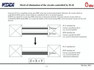
Adaptive Algorithm: AA1 • In the WS scheme (Cws = 5 + 5ρ) • registration - five database accesses • a call origination or termination - five database accesses • In the S scheme(Cs = 9 + ρ) • registration - nine database accesses (see Figure 6.7) • a call origination or termination - one database access (see Figure 6.8) • Cws=Cs if and on if ρ =1 • the S scheme outperforms the WS scheme (i.e., CS < Cws) if and only if ρ >1
Adaptive Algorithm: AA1 • The WS scheme : 0 <i < n - 1. • The S scheme : n < j < 2n - 1. • Let L • the number of call arrivals during the previous cycle. • If the steady state of the algorithm exists, then the transition probabilities for the finite automaton are: • ρ1 = Pr[L = 1], ρ2 = Pr[L = 0], and p3 = Pr[L > 1] • The AuC needs to maintain authentication scheme (AS) bits per user. • The VLR needs to maintain an AS bit per user
Adaptive Algorithm: AA1 • When the AuC is accessed for a registration operation, the AuC checks the following: Suppose that the algorithm is in state i. • If no call arrived during the previous cycle, the algorithm moves to state i - 1 for i > 0, and remains in the same state i for i = 0. • If exactly one call arrived during the previous cycle, the algorithm remains in the same state i. • If more than one call arrived during the previous cycle, the algorithm moves to state i + 1 for i < 2n - 1, and remains in the same state i for i=2n-1. • from state n -1 to state n from WS to S • from state n to state n – 1 from S to WS
Adaptive Algorithm : AA2 • requires only an AS bit in the AuC and VLRs to indicate whether the S scheme or the WS scheme is exercised. • At the beginning of a cycle, AA2 always exercises the WS scheme • AS bit is "WS" • After an originating or terminatingcall arrives, the AS bit is switched to "S," and the Sscheme is exercised. • Step 1 • When the first call arrives, the authentication message flow follows Figure 6.6 • when the AuC receives AuthenticationRequest (INVOKE) • AS bit "S" • SSD is sent to the VLR in the AuthenticationRequest (RETURN RESULT) message. • When the VLR receives the SSD • AS bit is set to "S” • At this moment, the S scheme is exercised.
Adaptive Algorithm : AA2 • Step 2 • For subsequent call arrivals in this cycle • the message flow in Figure 6.8 is followed. • Step 3 • At the end of the cycle-when the MS moves to a new LA • the authentication/registration occurs, the AuthenticationRequest messages are sent to the AuC. • Step 3a. • If the AS bit at the AuC is "WS," it implies that no call origination/ termination occurs during the cycle • Step 3b. • If the AS bit at the AuC is "S" The AS bit at the AuC is set to "WS." When the VLR receives the AuthenticationRequest (RETURN RESULT) message, • AS bit is set to "WS." • At the end of step 3, the WS scheme is exercised.