Introduction to Assembly Language Programming
Introduction to Assembly Language Programming. Overview of Assembly Language. Advantages:. Faster as compared to programs written using high-level languages Efficient memory usage Control down to bit level. Disadvantages:. Need to know detail hardware implementation Not portable


Introduction to Assembly Language Programming
E N D
Presentation Transcript
Introduction to Assembly Language Programming
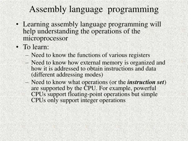
Overview of Assembly Language • Advantages: • Faster as compared to programs written using high-level languages • Efficient memory usage • Control down to bit level • Disadvantages: • Need to know detail hardware implementation • Not portable • Slow to development and difficult to debug • Basic components in assembly Language: Instruction, Directive, Label, and Comment
BIU Elements • Instruction Queue: the next instructions or data can be fetched from memory while the processor is executing the current instruction • The memory interface is slower than the processor execution time so this speeds up overall performance • Segment Registers: • CS, DS, SS and ES are 16b registers • Used with the 16b Base registers to generate the 20b address • Allow the 8086/8088 to address 1MB of memory • Changed under program control to point to different segments as a program executes • Instruction Pointer (IP) contains the Offset Address of the next instruction, the distance in bytes from the address given by the current CS register
Exercise: 20-bit Addressing • CS contains 0A820h,IP contains 0CE24h. What is the resulting physical address? • CS contains 0B500h, IP contains 0024h. What is the resulting physical address?
Example of Assembly Language Program ;NUMOFF.ASM: Turn NUM-LOCK indicator off. .MODEL SMALL .STACK .CODE .STARTUP MOV AX,40H ;set AX to 0040H D1: MOV DS,AX ;load data segment with 0040H MOV SI,17H ;load SI with 0017H AND BYTE PTR [SI],0DFH ;clear NUM-LOCK bit .EXIT END Comments Assembly directive Instructions Assembly directive Label
Instruction Format • General Format of Instructions Label: Opcode Operands; Comment • Label: It is optional. It provides a symbolic address that can be used in branch instructions • Opcode: It specifies the type of instructions • Operands: Instructions of 80x86 family can have one, two, or zero operand • Comments: Only for programmers’ reference • Machine Code Format Opcode Mode Operand1 Operand2 MOV AL, BL 1 0 0 0 1 0 0 0 1 1 0 0 0 0 1 1 Register mode MOV
What is the Meaning of Addressing Modes? • When a CPU executes an instruction, it needs to know where to get data and where to store results. Such information is specified in the operand fields of the instruction. MOV AL, BL 1 0 0 0 1 0 0 0 1 1 0 0 0 0 1 1 Opcode Mode Operand1 Operand2 • An operand can be: • A datum • A register location • A memory location • Addressing modes define how the CPU finds where to get data and where to store results
Immediate Addressing • Data needed by the processor is contained in the instruction For Example: move 7 to register AL AL 7 MOV AL, 7 AH Machine code of MOV AL, 7 1 0 1 1 0 0 0 0 0 0 0 0 0 1 1 1 7 AL Indicate 8-bit data operation Move an immediate datum to a register
Register Addressing • Operands of the instruction are the names of internal register • The processor gets data from the register locations specified by instruction operands For Example: move the value of register BL to register AL MOV AL, BL AH AL BL BH • If AX = 1000H and BX=A080H, after the execution of MOV AL, BL what are the new values of AX and BX? In immediate and register addressing modes, the processor does not access memory. Thus, the execution of such instructions are fast.
Direct Addressing • The processor accesses a memory location • The memory location is determined by the value of segment register DS and the displacement (offset) specified in the instruction operand field DS 10H + Displacement = Memory location • Example: assume DS = 1000H, AX = 1234H DS: 1 0 0 0 _ + Disp: 7 0 0 0 MOV [7000H], AX 1 7 0 0 0 AH AL 12 34 12 17001H 17000H 34
Register Indirect Addressing • One of the registers BX, BP, SI, DI appears in the instruction operand field. Its value is used as the memory displacement value. For Example: MOV DL, [SI] • Memory address is calculated as following: BX SI DI DS 10H + = Memory address SS BP • If BX, SI, or DI appears in the instruction operand field, segment register DS is used in address calculation • If BP appears in the instruction operand field, segment register SS is used in address calculation
Register Indirect Addressing • Example 1: assume DS = 0800H, SI=2000H DH DL MOV DL, [SI] 12 0A000H 12 DS: 0 8 0 0 _ + SI: 2 0 0 0 memory 0 A 0 0 0 • Example 2: assume SS = 0800H, BP=2000H, DL = 7 MOV [BP], DL ?
Based Addressing • The operand field of the instruction contains a base register (BX or BP) and an 8-bit (or 16-bit) constant (displacement) For Example: MOV AX, [BX+4] • Calculate memory address DS BX 10H + + Displacement = Memory address SS BP • If BX appears in the instruction operand field, segment register DS is used in address calculation • If BP appears in the instruction operand field, segment register SS is used in address calculation What’s difference between register indirect addressing and based addressing?
Based Addressing • Example 1: assume DS = 0100H, BX=0600H AH AL MOV AX, [BX+4] C0 B0 C0 01605H DS: 0 1 0 0 _ + BX: 0 6 0 0 + Disp.: 0 0 0 4 01604H B0 0 1 6 0 4 memory • Example 2: assume SS = 0A00H, BP=0012H, CH = ABH MOV [BP-7], CH ?
Indexed Addressing • The operand field of the instruction contains an index register (SI or DI) and an 8-bit (or 16-bit) constant (displacement) For Example: MOV [DI-8], BL • Calculate memory address SI DS 10H + + Displacement = Memory address DI • Example: assume DS = 0200H, DI=0030H BL = 17H MOV [DI-8], BL BH BL DS: 0 2 0 0 _ + DI: 0 0 3 0 - Disp.: 0 0 0 8 17 02028H 17 0 2 0 2 8 memory
Based Indexed Addressing • The operand field of the instruction contains a base register (BX or BP) and an index register For Example: MOV [BP] [SI], AH MOV [BP+SI], AH or • Calculate memory address DS BX 10H + + {SI or DI} = Memory address SS BP • If BX appears in the instruction operand field, segment register DS is used in address calculation • If BP appears in the instruction operand field, segment register SS is used in address calculation
Based Indexed Addressing • Example 1: assume SS = 2000H, BP=4000H, SI=0800H, AH=07H AH AL MOV [BP] [SI], AH 07 07 24800H SS: 2 0 0 0 _ + BP: 4 0 0 0 + SI.: 0 8 0 0 2 4 8 0 0 memory • Example 2: assume DS = 0B00H, BX=0112H, DI = 0003H, CH=ABH MOV [BX+DI], CH ?
Based Indexed with Displacement Addressing • The operand field of the instruction contains a base register (BX or BP), an index register, and a displacement For Example: MOV CL, [BX+DI+2080H] • Calculate memory address DS BX 10H + + {SI or DI} + Disp. = Memory address SS BP • If BX appears in the instruction operand field, segment register DS is used in address calculation • If BP appears in the instruction operand field, segment register SS is used in address calculation
Based Indexed with Displacement Addressing • Example 1: assume DS = 0300H, BX=1000H, DI=0010H CH CL MOV CL, [BX+DI+2080H] 20 DS: 0 3 0 0 _ + BX: 1 0 0 0 + DI.: 0 0 1 0 + Disp. 2 0 8 0 06090H 20 memory 0 6 0 9 0 • Example 2: assume SS = 1100H, BP=0110H, SI = 000AH, CH=ABH MOV [BP+SI+0010H], CH ?
Instruction Types • Data transfer instructions • String instructions • Arithmetic instructions • Bit manipulation instructions • Loop and jump instructions • Subroutine and interrupt instructions • Processor control instructions An excellent website about 80x86 instruction set: http://www.penguin.cz/~literakl/intel/intel.html Another good reference is in the tutorial of 8086 emulator
Addressing Modes Addressing Modes Examples • Immediate addressing MOV AL, 12H • Register addressing MOV AL, BL • Direct addressing MOV [500H], AL • Register Indirect addressing MOV DL, [SI] • Based addressing MOV AX, [BX+4] • Indexed addressing MOV [DI-8], BL • Based indexed addressing MOV [BP+SI], AH • Based indexed with displacement addressing MOV CL, [BX+DI+2] Exceptions • String addressing • Port addressing (e.g. IN AL, 79H)
15 0 OF DF IF TF SF ZF AF PF CF Flag Register • Flag register contains information reflecting the current status of a microprocessor. It also contains information which controls the operation of the microprocessor. • Status Flags • Control Flags CF: Carry flag PF: Parity flag AF: Auxiliary carry flag ZF: Zero flag SF: Sign flag OF: Overflow flag IF: Interrupt enable flag DF: Direction flag TF: Trap flag
Flags Commonly Tested During the Execution of Instructions • There are five flag bits that are commonly tested during the execution of instructions • Sign Flag (Bit 7), SF: 0 for positive number and 1 for negative number • Zero Flag (Bit 6), ZF: If the ALU output is 0, this bit is set (1); otherwise, it is 0 • Carry Flag (Bit 0), CF: It contains the carry generated during the execution • Auxiliary Carry, AF: Depending on the width of ALU inputs, this flag (Bit 4) bit contains the carry generated at bit 3 (or, 7, 15) of the 8088 ALU • Parity Flag (bit2), PF: It is set (1) if the output of the ALU has even number of ones; otherwise it is zero
Data Transfer Instructions • MOV Destination, Source • Move data from source to destination; e.g. MOV [DI+100H], AH • It does not modify flags • For 80x86 family, directly moving data from one memory location to another memory location is not allowed MOV [SI], [5000H] • When the size of data is not clear, assembler directives are used ? MOV [SI], 0 • BYTE PTR MOV BYTE PTR [SI], 12H • WORD PTR MOV WORD PTR [SI], 12H • DWORD PTR MOV DWORD PTR [SI], 12H • You can not move an immediate data to segment register by MOV MOV DS, 1234H
Instructions for Stack Operations • What is a Stack ? • A stack is a collection of memory locations. It always follows the rule of last-in-firs-out • Generally, SS and SP are used to trace where is the latest date written into stack • PUSH Source • Push data (word) onto stack • It does not modify flags • For Example: PUSH AX (assume ax=1234H, SS=1000H, SP=2000H before PUSH AX) 1000:1FFD ?? 1000:1FFD ?? 1000:1FFE ?? SS:SP 1000:1FFE 34 1000:1FFF ?? 1000:1FFF 12 SS:SP 1000:2000 ?? 1000:2000 ?? 12 34 AX Before PUSH AX, SP = 2000H After PUSH AX, SP = 1FFEH • Decrementing the stack pointer during a push is a standard way of implementing stacks in hardware
Instructions for Stack Operations • PUSHF • Push the values of the flag register onto stack • It does not modify flags • POP Destination • Pop word off stack • It does not modify flags • For example: POP AX 1000:1FFD ?? 1000:1FFD ?? SP 1000:1FFE 34 1000:1FFE 34 1000:1FFF 12 1000:1FFF 12 1000:2000 EC SP 1000:2000 EC 12 34 AX After POP AX, SP = 2000H Before POP, SP = 1FFEH • POPF • Pop word from the stack to the flag register • It modifies all flags
Data Transfer Instructions • SAHF • Store data in AH to the low 8 bits of the flag register • It modifies flags: AF, CF, PF, SF, ZF • LAHF • Copies bits 0-7 of the flags register into AH • It does not modify flags • LDS Destination Source • Load 4-byte data (pointer) in memory to two 16-bit registers • Source operand gives the memory location • The first two bytes are copied to the register specified in the destination operand; the second two bytes are copied to register DS • It does not modify flags • LES Destination Source • It is identical to LDS except that the second two bytes are copied to ES • It does not modify flags
Data Transfer Instructions • LEA Destination Source • Transfers the offset address of source (must be a memory location) to the destination register • It does not modify flags • XCHG Destination Source • It exchanges the content of destination and source • One operand must be a microprocessor register, the other one can be a register or a memory location • It does not modify flags • XLAT • Replace the data in AL with a data in a user defined look-up table • BX stores the beginning address of the table • At the beginning of the execution, the number in AL is used as the index of the look-up table • It does not modify flags
String Instructions • String is a collection of bytes, words, or long-words that can be up to 64KB in length • String instructions can have at most two operands. One is referred to as source string and the other one is called destination string • Source string must locate in Data Segment and SI register points to the current element of the source string • Destination string must locate in Extra Segment and DI register points to the current element of the destination string DS : SI ES : DI S S 0510:0000 53 02A8:2000 53 0510:0001 48 H 02A8:2001 48 H 0510:0002 4F 02A8:2002 4F O O 50 50 0510:0003 02A8:2003 P P P P 50 50 0510:0004 02A8:2004 E I 0510:0005 45 02A8:2005 49 52 R 4E N 0510:0006 02A8:2006 Source String Destination String
Repeat Prefix Instructions • REP String Instruction • The prefix instruction makes the microprocessor repeatedly execute the string instruction until CX decrements to 0 (During the execution, CX is decreased by one when the string instruction is executed one time). • For Example: MOV CX, 5 REP MOVSB By the above two instructions, the microprocessor will execute MOVSB 5 times. • Execution flow of REP MOVSB:: While (CX!=0) { CX = CX –1; MOVSB; } Check_CX: If CX!=0 Then CX = CX –1; MOVSB; goto Check_CX; end if OR
Repeat Prefix Instructions • REPZ String Instruction • Repeat the execution of the string instruction until CX=0 or zero flag is clear • REPNZ String Instruction • Repeat the execution of the string instruction until CX=0 or zero flag is set • REPE String Instruction • Repeat the execution of the string instruction until CX=0 or zero flag is clear • REPNE String Instruction • Repeat the execution of the string instruction until CX=0 or zero flag is set
Direction Flag • Direction Flag (DF) is used to control the way SI and DI are adjusted during the execution of a string instruction • DF=0, SI and DI will auto-increment during the execution; otherwise, SI and DI auto-decrement • Instruction to set DF: STD; Instruction to clear DF: CLD • Example: CLD MOV CX, 5 REP MOVSB DS : SI S 0510:0000 53 SI CX=5 0510:0001 48 H SI CX=4 0510:0002 4F O SI CX=3 50 0510:0003 P SI CX=2 At the beginning of execution, DS=0510H and SI=0000H P 50 SI CX=1 0510:0004 E 0510:0005 45 SI CX=0 52 R 0510:0006 Source String
String Instructions • MOVSB (MOVSW) • Move byte (word) at memory location DS:SI to memory location ES:DI and update SI and DI according to DF and the width of the data being transferred • It does not modify flags • Example: DS : SI ES : DI S MOV AX, 0510H MOV DS, AX MOV SI, 0 MOV AX, 0300H MOV ES, AX MOV DI, 100H CLD MOV CX, 5 REP MOVSB 0510:0000 53 0300:0100 0510:0001 48 H 0510:0002 4F O 50 0510:0003 P P 50 0510:0004 E 0510:0005 45 52 R 0510:0006 Source String Destination String
String Instructions • CMPSB (CMPSW) • Compare bytes (words) at memory locations DS:SI and ES:DI; update SI and DI according to DF and the width of the data being compared • It modifies flags • Example: Assume: ES = 02A8H DI = 2000H DS = 0510H SI = 0000H DS : SI ES : DI S 0510:0000 53 S 53 02A8:2000 0510:0001 48 H 48 H 02A8:2001 0510:0002 4F 4F O O 02A8:2002 CLD MOV CX, 9 REPZ CMPSB 50 50 0510:0003 P P 02A8:2003 P 50 P 50 0510:0004 02A8:2004 E 0510:0005 45 I 49 02A8:2005 52 R 0510:0006 4E N 02A8:2006 What’s the values of CX after The execution? Source String Destination String
String Instructions • SCASB (SCASW) • Move byte (word) in AL (AX) and at memory location ES:DI; update DI according to DF and the width of the data being compared • It modifies flags • LODSB (LODSW) • Load byte (word) at memory location DS:SI to AL (AX); update SI according to DF and the width of the data being transferred • It does not modify flags • STOSB (STOSW) • Store byte (word) at in AL (AX) to memory location ES:DI; update DI according to DF and the width of the data being transferred • It does not modify flags
Arithmetic Instructions • ADD Destination, Source • Destination + Source Destination • Destination and Source operands can not be memory locations at the same time • It modifies flags AF CF OF PF SF ZF • ADC Destination, Source • Destination + Source + Carry Flag Destination • Destination and Source operands can not be memory locations at the same time • It modifies flags AF CF OF PF SF ZF • INC Destination • Destination + 1 Destination • It modifies flags AF OF PF SF ZF (Note CF will not be changed) • DEC Destination • Destination - 1 Destination • It modifies flags AF OF PF SF ZF (Note CF will not be changed)
Arithmetic Instructions • SUB Destination, Source • Destination - Source Destination • Destination and Source operands can not be memory locations at the same time • It modifies flags AF CF OF PF SF ZF • SBB Destination, Source • Destination - Source - Carry Flag Destination • Destination and Source operands can not be memory locations at the same time • It modifies flags AF CF OF PF SF ZF • CMP Destination, Source • Destination – Source (the result is not stored anywhere) • Destination and Source operands can not be memory locations at the same time • It modifies flags AF CF OF PF SF ZF (if ZF is set, destination = source)
Arithmetic Instructions • MUL Source • Perform unsigned multiply operation • If source operand is a byte, AX = AL * Source • If source operand is a word, (DX AX) = AX * Source • Source operands can not be an immediate data • It modifies CF and OF (AF,PF,SF,ZF undefined) • IMUL Source • Perform signed binary multiply operation • If source operand is a byte, AX = AL * Source • If source operand is a word, (DX AX) = AX * Source • Source operands can not be an immediate data • It modifies CF and OF (AF,PF,SF,ZF undefined) • Examples: MOV AL, 20H MOV CL, 80H IMUL CL MOV AL, 20H MOV CL, 80H MUL CL
Arithmetic Instructions • DIV Source • Perform unsigned division operation • If source operand is a byte, AL = AX / Source; AH = Remainder of AX / Source • If source operand is a word, AX=(DX AX)/Source; DX=Remainder of (DX AX)/Source • Source operands can not be an immediate data • IDIV Source • Perform signed division operation • If source operand is a byte, AL = AX / Source; AH = Remainder of AX / Source • If source operand is a word, AX=(DX AX)/Source; DX=Remainder of (DX AX)/Source • Source operands can not be an immediate data • Examples: MOV AL, -5 MOV BL, 2 IDIV BL MOV AX, 5 MOV BL, 2 DIV BL
Arithmetic Instructions • NEG Destination • 0 – Destination Destination (the result is represented in 2’s complement) • Destination can be a register or a memory location • It modifies flags AF CF OF PF SF ZF • CBW • Extends a signed 8-bit number in AL to a signed 16-bit data and stores it into AX • It does not modify flags • CWD • Extends a signed 16-bit number in AX to a signed 32-bit data and stores it into DX and AX. DX contains the most significant word • It does not modify flags • Other arithmetic instructions: DAA, DAS, AAA, AAS, AAM, AAD
Logical Instructions • NOT Destination • Inverts each bit of the destination operand • Destination can be a register or a memory location • It does not modify flags • AND Destination, Source • Performs logic AND operation for each bit of the destination and source; stores the result into destination • Destination and source can not be both memory locations at the same time • It modifies flags: CF OF PF SF ZF • OR Destination, Source • Performs logic OR operation for each bit of the destination and source; stores the result into destination • Destination and source can not be both memory locations at the same time • It modifies flags: CF OF PF SF ZF
Logical Instructions • XOR Destination, Source • Performs logic XOR operation for each bit of the destination and source; stores the result into destination • Destination and source can not be both memory locations at the same time • It modifies flags: CF OF PF SF ZF • TEST Destination, Source • Performs logic AND operation for each bit of the destination and source • Updates Flags depending on the result of AND operation • Do not store the result of AND operation anywhere
Bit Manipulation Instructions • SHL(SAL) Destination, Count • Left shift destination bits; the number of bits shifted is given by operand Count • During the shift operation, the MSB of the destination is shifted into CF and zero is shifted into the LSB of the destination • Operand Count can be either an immediate data or register CL • Destination can be a register or a memory location • It modifies flags: CF OF PF SF ZF CF Destination 0 MSB LSB • SHR Destination, Count • Right shift destination bits; the number of bits shifted is given by operand Count • During the shift operation, the LSB of the destination is shifted into CF and zero is shifted into the MSB of the destination • Operand Count can be either an immediate data or register CL • Destination can be a register or a memory location • It modifies flags: CF OF PF SF ZF 0 Destination CF MSB LSB
Bit Manipulation Instructions • SAR Destination, Count • Right shift destination bits; the number of bits shifted is given by operand Count • The LSB of the destination is shifted into CF and the MSB of the destination remians the same • Operand Count can be either an immediate data or register CL • Destination can be a register or a memory location • It modifies flags: CF PF SF ZF Destination CF MSB LSB
Bit Manipulation Instructions • ROL Destination, Count • Left shift destination bits; the number of bits shifted is given by operand Count • The MSB of the destination is shifted into CF, it also goes to the LSB of the destination • Operand Count can be either an immediate data or register CL • Destination can be a register or a memory location • It modifies flags: CF OF MSB LSB CF Destination • ROR Destination, Count • Right shift destination bits; the number of bits shifted is given by operand Count • The LSB of the destination is shifted into CF, it also goes to the MSB of the destination • Operand Count can be either an immediate data or register CL • Destination can be a register or a memory location • It modifies flags: CF OF MSB LSB Destination CF
Bit Manipulation Instructions • RCL Destination, Count • Left shift destination bits; the number of bits shifted is given by operand Count • The MSB of the destination is shifted into CF; the old CF value goes to the LSB of the destination • Operand Count can be either an immediate data or register CL • Destination can be a register or a memory location • It modifies flags: CF OF PF SF ZF MSB LSB CF Destination • RCR Destination, Count • Right shift destination bits; the number of bits shifted is given by operand Count • The LSB of the destination is shifted into CF, the old CF value goes to the MSB of the destination • Operand Count can be either an immediate data or register CL • Destination can be a register or a memory location • It modifies flags: CF OF PF SF ZF MSB LSB Destination CF
Program Transfer Instructions • JMP Target • Unconditional jump • It moves microprocessor to execute another part of the program • Target can be represented by a label, immediate data, registers, or memory locations • It does not affect flags • The execution of JMP instruction JMP 1234H : 2000H Current instruction JMP 1234H CS Jump 2000H IP Next Instruction Address 14340H Next instruction
Program Transfer Instructions • Intrasegment transfer v.s. Intersegment transfer • Intrasegment transfer: the microprocessor jumps to an address within the same segment • Intersegment transfer: the microprocessor jumps to an address in a difference segment • Use assembler directive near and far to indicate the types of JMP instructions • For intrasegment transfer, we can provide only new IP value in JMP instructions. For Example: JMP 1000H • For intersegment transfer, we need provide both new CS and IP values in JMP instructions For Example: JMP 2000H : 1000H • Direct Jump v.s. Indirect Jump • Direct Jump: the target address is directly given in the instruction • Indirect Jump: the target address is contained in a register or memory location • Short Jump • If the target address is within +127 or –128 bytes of the current instruction address, the jump is called a short jump • For short jumps, instead of specifying the target address, we can specify the relative offset (the distance between the current address and the target address) in JMP instructions.