Case Studies in MEMS
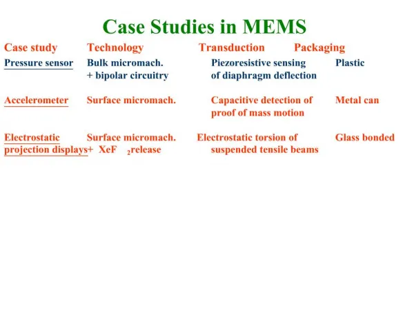
Case Studies in MEMS. Case study Technology Transduction Packaging. Pressure sensor Bulk micromach. Piezoresistive sensing Plastic + bipolar circuitry of diaphragm deflection

Case Studies in MEMS
E N D
Presentation Transcript
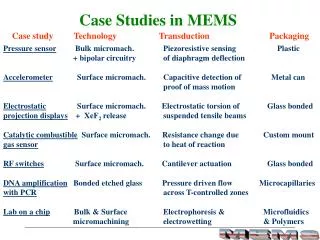
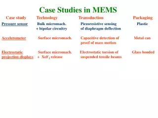
Case Studies in MEMS Case study Technology Transduction Packaging Pressure sensor Bulk micromach. Piezoresistive sensing Plastic + bipolar circuitry of diaphragm deflection Accelerometer Surface micromach. Capacitive detection of Metal can proof of mass motion Electrostatic Surface micromach. Electrostatic torsion of Glass bonded projection displays + XeF2 release suspended tensile beams
Optical MEMS • Why are MEMS used here? • - Structures are the same dimensions as the wavelength • - Small displacement has a large effect, can be used for SWITCHING • * Interferometric devices • * Scanning devices • - A photon has no mass, easy to deflect light • Can fabricate large-scale systems, • (e.g. 1000 X 1000 displays as in the • Digital Micro-mirror device) Courtesy: H. Toshiyoshi
Applications of Electrostatic projection displays Courtesy: H. Toshiyoshi
Applications of Electrostatic projection displays • Control of light through: • Reflection : Texas Instruments • (DMD: Digital Micromirror Device) • (2) Diffraction: Silicon light Machines • (GLV: Grating Light Valve)
Texas Instruments’ Digital Micro-mirror Device (DMD) The most advanced display technology to date • Each rotatable mirror is a pixel • 1024 shades of gray and 35 trillion colors possible • use in projection systems, TV and theaters
Distinguishing features of a DMD H. Toshiyoshi • Higher brightness and contrast • Gray scale achieved by digital and analog modulation • - Digital: Pulse Width Modulation (PWM) • - Analog: Spatial Light Modulation (SLM) • Compact, low weight and low power Portable system
History (1): Si cantilever based light modulator Petersen, K.E., “Micromechanical light modulator array fabricated on Silicon”, Applied Physics Letters, 31, pp. 521-523, 1977 • Electrically actuated, individually addressable cantilevers • Pull -in • SiO2 structural layer • Si sacrificial layer
History(2): Torsional electrostatic light modulator Petersen, K.E., “Silicon torsional scanning mirror”, IBM Journal of Research & Dev., 24, pp. 631-637, 1980 • Electrically actuated torsion mirrors • 1012 cycles, with ± 1o rotation • Bulk micromachining of Silicon
History (3): Deformable Mirror Devices L. Hornbeck, “Deformable Mirror Spatial Light Modulator”, SPIE, vol. 1150, p.86, 1989 Elastomer based Cantilever based Membrane based Torsion: Amplitude dependent modulation Cantilever based: Phase dependent modulation
Digital Micro-mirror device www.dlp.com
DMD Fabrication (6 photomask layers) DMD superstructure on CMOS circuitry • Surface micromachining process • Hinge: Aluminum alloy (Al, Ti, Si) • (50-100 nm thick) • Mirror: Aluminum (200-500 nm thick) • Aluminum : structural material • DUV hardened photoresist: sacrificial material • Dry release (plasma etching) reduces stiction Courtesy: H. Toshiyoshi
Digital Micro-mirror device www.dlp.com
a Principle of Operation Balancing electrical torque with mechanical torque Telectrical is proportional to (voltage)2 Tmechanicalis proportional to (deflection, a)
Electrostatic model of a torsion mirror Arc length Electric field x Mirror r d a q V Torsion beam • Neglect fringing electric field • Neglect any residual stress
x Mirror W: width L: length t: thickness r d a q V Torsion beam Electrostatic model of a torsion mirror Electrostatic torque (Telec) = Mechanical torque (Tmech) = e.g. polysilicon, G = 73 GPa r= 2.35 g/cm3
Balancing electrical and mechanical Torques Graph Courtesy, M. Wu
Energy domain model The torsion mirror as a capacitive device
Calculation of capacitance From: M. Wu and S. Senturia
Approximate solution - stable angle and pull-in voltage From: M. Wu and S. Senturia
x r d a q V x r d a q V-v V+v Schemes of Torsion Mirror operation Pull-in voltageScan angleAngle-voltage Single side drive Low Small Non-linear High Large Linear Push-pull drive Bias voltages
1-DMD chip system • Can create 1024 shades of gray • used in projectors, TVs and home theater systems
2-DMD chip system • Can create 16.7 million shades of color • used in projectors, TVs and home theater systems
3-DMD chip system is used for higher resolutions • For movie projection and other high end applications • (35 trillion colors can be generated)
Grating Light Valve (GLV) - Silicon Light Machines (www.siliconlight.com) Courtesy: M.C. Wu Reflection : broad band Diffraction :Wavelength (l) dependent 1 mirror/pixel (2-D array) 6 ribbons/pixel (1-D array) Larger displacements Displacement: l/4 (msec time response) (nanosecond response) Voltage controlled A fixed angle Constant intensity Diffracted intensity varied by voltage
Mode of Operation A diffraction grating of 6 beams 1 pixel
By using a different spacing between ribbons, one can create different color-oriented pixels
MEMS in Optical Communications • Very quick switching (> 100 kHz), low losses, • Low cost, batch fabrication Optical Micro-mirrors used with Add-Drop multiplexers 1 X 2 Optical switch Optical fibers Bell Labs research
MEMS Micro Optical Bench Integrable Micro-Optics MEMS Actuators Opto MEMS Slide courtesy: H. Toshiyoshi
Scratch Drive Actuator • Large total displacements can be achieved (1 mm) @ 100 Hz – 100 KHz • Increments / forward movement as small as 10 nm • voltages required are large Scratch actuator movement Akiyama, J. MEMS, 2, 106, 1993 Voltage applied
MEMS in 3-dimensions “Microfabricated hinges”, K. Pister et al, Sensors & Actuators A, vol. 33, pp. 249-256, 1992 • Assembly of three-dimensional structures • Large vertical resolution and range Surface micromachining based Other variants of the hinge H. Toshiyoshi
MEMS in Optical Communications • Very quick switching (> 100 kHz), low losses, • Low cost, batch fabrication Optical Micro-mirrors used with Add-Drop multiplexers 1 X 2 Optical switch Optical fibers Bell Labs research