Download
1 / 38
380 likes | 511 Vues
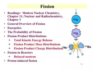
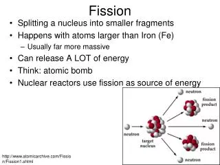
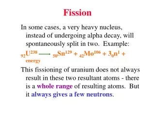
The accurate simulation and design of Generation IV and Accelerator Driven Systems (ADS) necessitate high-quality nuclear data. Current data libraries exhibit discrepancies and insufficient fission cross-section data from 1 eV to 1 MeV, impacting thorium fuel cycles. The n_TOF initiative has conducted extensive measurements of neutron-induced fission in actinides, utilizing advanced detection setups in their dedicated facility. This document details experimental setups, data acquisition systems, outcomes of fission measurements, and the significance of improved nuclear data for reactor design.

E N D
Nuclear data needs • Simulation and design of Gen-IV and ADS systems require accurate nuclear data • Current data libraries present important discrepancies and lacks.
Fission Cross Sections 1eV 1MeV
Neutron Capture decay Thorium fuel • 232Th + n 233Th 233Pa 233U (fissile) 232U 233U 234U 235U 236U 237U 238U 231Pa 232Pa 233Pa 234Pa 235Pa 230Th 231Th 232Th 233Th 234Th
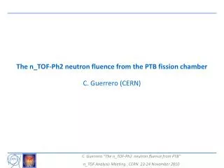
Experimental Campaign • A set of measurements of neutron-induced fission in actinides was launched within the FP5. • Fission measurements in the framework of the n_TOF Collaboration and construction of the n_TOF facility.
Fission Chambers @ n_TOF PPAC chamber FIC chamber
… n_TOF Fission Ionization Chamber Assembly Ionization chamber Gas used: Ar (90 %) CF4 (10 %). Gas pressure: 720 mbar Electric field: 600 V/cm Gap pitch: 5 mm Deposit diameter: 5 cm Deposit thickness: 125 µg/cm Support thickness: 100 µm (Al) Deposits on both sides. Electrode diameter: 12 cm Electrode thick.: 15 µm (Al) Windows diameter: 12 cm (KAPTON 125 µm)
List of Targets ----FIC0---- 235U - 47mg (3 targets) 238U - 110mg (3 targets) 232Th - 80mg (2 targets) 236U - 20mg (2 targets) 237Np - 10mg (1 target) 234U - 34mg (6 targets) ----FIC1---- 235U - 30mg (1 targets) 238U - 90mg (2 targets) 241Am - 2mg (4 targets) 243Am - 10mg (4 targets) 245Cm - 2mg (2 target) 233U - 20mg (2 targets)
Fission Chambers @ n_TOF PPAC chamber FIC chamber
PPACs @ n_TOF • 10 detectors 9 targets • U-234(2) and Th-232(5) • Two reference targets: U-235 y U-238 • Less than 1 % of flux attenuation in the full setup.
Measured isotopes • Minor actinide : 237Np • Thorium cycle : 233U, 234U, 232Th • Spallation target : 209Bi, natPb • Reference isotopes : 235U, 238U
Fission Detection Setup • Fissile target in a thin backing sandwiched by two detectors Detection of both fission fragments in coincidence. • Fission event reconstruction: target position and emission angle. Efficiency limited by the cut at large angles.
U-234: singles U-234: coincidences Discrimination with coincidences
Cathode Positioning (I) • Positioning by using stripped cathodes and delay line readout. • The cathode signal is split in the delay line and transmitted to both ends Stripped Cathode Delay Line
Cathode positioning (II) Diagonal condition: (Tch1-Tanode)+(Tch2-Tanode)=DLT DLT: Total delay line length (~320 ns) The time difference between both cathode ends provides the position of the signal.
Targets (I) Epoxy frame Uranium target 80 mm Ø 300 µg/cm2 2 µm Al backing
Targets (II) • Measurement of thickness and homogeneity by alpha counting and/or proton scattering. • High purity samples (> 99 % for U-234). 234U Y (mm) X (mm) activity
The n_TOF Data Acquisition System • The n_TOF DAQ consists of 54 flash ADC channels with 8 bit amplitude resolution and sampling of 500 MSample/s. • The full history of EVERY detector (BaF2 crystals and monitors) is digitised during a period of 16 ms (0.7 eV < En < 20 GeV) and recorded permanently on tape. Very useful feature since the raw data can be always re-investigated. • The system has nearly zero dead time. • 7.5 TB disk space for temporary storage. • Typical data rate of 2-3 TB/day on tape after compression. • Pulse shape analysis is performed on the fly at the LXBATCH Linux Batch Farm at CERN (30 CPUs exclusively dedicated) and stored in highly compressed Data Summary Tapes. • Quasi on-line analysis of the data with full statistics. One of the big successes of n_TOF. Many TOF facilities are following the n_TOF example and moving to digital electronics!
PPAC signal analysis • Negative loop should be first • Xpos-Xneg < constant • const1 < Hneg/Hpos < const2
HFF LFF Light vs. Heavy Fission Fragments Target 0 Energy < 10 MeV (Assymetric fission)
Light vs. Heavy Fission Fragments Cathode signals for En around 1 MeV
Cross Section Analysis • (E): fission cross section • n (x,y,E): fission rate obtained from raw data • (x,y): surface density of the target • (E): detection setup efficiency a(x,y,E)/ b(x,y,E) ≈ 1 ± 0.01 (1%)
50º 50º Angular acceptance Simulations Measurements
Log E =6.0 Log E =5.8 Log E =5.9 Cos () Cos () Cos () Log E =5.4 Log E =5.6 Log E =5.5 Fission Fragment Angular Distribution U-234 FFAD for neutron energies near the fission threshold
Y (mm) X (mm) n_TOF beam at fission campaign • Neutron spectrum in the whole energy range. • Beam profile
U234(n,f) U234 resonances
234U Previous data (IRMM report) Better energy resolution achieved at nTOF
Np237(n,f) Np237 resonances
Conclusions • The coincidence method has been used to obtain the fission results for the extensive n_TOF neutron energy range. • Th233, U234, Np237 results have been already produced and U233 is in progress. • Important discrepancies have been found in the Np237 resonance region.
Fission Chamber @ n_TOF PPAC chamber FIC chamber
n_TOF CERN
FIC Design • Gas – Ar 90%+CF4 10% • Pressure – 600 mbar • Distance – 5 mm • HV – 300 V • 17 targets in the beam • “noise” electrode