FLEXIBLE OVERLAYS FOR RIGID PAVEMENTS
230 likes | 921 Vues
FLEXIBLE OVERLAYS FOR RIGID PAVEMENTS. Camille Crichton- Sumners Manager, Bureau of Research NJ Department of Transportation http://www.state.nj.us/transportation/refdata/research 609-530-5966

FLEXIBLE OVERLAYS FOR RIGID PAVEMENTS
E N D
Presentation Transcript
FLEXIBLE OVERLAYS FOR RIGID PAVEMENTS Camille Crichton-Sumners Manager, Bureau of Research NJ Department of Transportation http://www.state.nj.us/transportation/refdata/research 609-530-5966 Principal Investigator: Tom Bennert, Ph.D. Rutgers University, Center for Advanced Infrastructure and Transportation Project Number:FHWA-NJ-2009-014
Problem Statement • PCC reconstruction costly and timely • Rubblization is option, but require minimum of 6 inches hot mix asphalt cover • HMA cover requirements restricts area with overhead clearance and/or guide rail issues • PCC rehabilitation generally not successful • Most simple rehabilitation technique – Hot Mix Asphalt (HMA) Overlay • Unfortunately, high deflections at PCC joints/cracks creates excessive straining in HMA overlay • Most cases, cracking initiated in HMA above crack/joint in PCC (called Reflective Cracking)
Problem Statement - continued • When reflective crack reaches pavement surface • Affects overall integrity of pavement • Smoothness – intermittent cracking also affects safety • Pathway for water intrusion • Area for immediate raveling • Little guidance on how to design HMA overlays for PCC pavements • HMA material/mixture selection • Immediate need to develop a rational methodology of HMA mixture selection/design methodology for overlaying PCC pavements
ResearchApproach • Literature Review • National Survey (Distributed to all 50 states – state pavement designers and materials engineers) • Develop Methodology • Based on information collected • Develop Test Sites (PA, Mass, NJ) • Field Evaluation • Laboratory Evaluation • Analyze collected data and evaluate prediction methodology • Develop a Decision Tree Methodology for HMA Overlay Design for PCC Pavements • Conclusions/Recommendations
Major Conclusions from Literature Review • Major mechanism generating reflective cracking is tensile strain at bottom of PCC • Shearing at joint/crack an accelerator not initiator (if cracking can be mitigated, shearing should not result in cracking) • All PCC pavements respond differently in both vertical and horizontal mode – need methods to test/identify potential magnitude of movements (Load and Climate related) • Best mechanical laboratory tests for simulation • Vertical Bending: Flexural Beam Fatigue • Horizontal Deflection: Overlay Tester (HMA) and Coefficient of Thermal Expansion (PCC) • Critical cracking condition • Air temperatures already low and climate under-going a cooling cycle • HMA brittle – more crack prone to vertical and horizontal movements • PCC slabs contracting
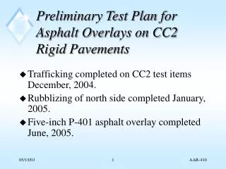
Major Conclusions from Literature Review - continued • No consensus exists on successful mitigation methods • Did indicate geotextiles/fabrics poor in colder climates • Strain-tolerant interlayers (asphalt mixtures) excellent fracture resistance compared to conventional dense graded mixtures • Help to reduce strain magnitudes • Residual strain still may be too high for conventional mixes • When field deformations at PCC joint/crack are accurately measured, these deformations can be used in laboratory to simulate field movements • Provides reasonable estimates on reflective cracking life
National Survey on Reflective Cracking 28 Responding States WA ME MT ND VT MN OR NH MA ID WI NY SD RI WY MI CT PA NJ IA NE NV OH DE IN IL UT MD CO WV VA KS MO CA KY NC TN AZ OK AR SC NM GA AL MS TX LA FL AK Responded No Response HI
Summary of Survey Responses • Reflective cracking appeared to occur equally at different traffic levels and base types • General trends to greater reflective cracking life at stronger base materials (PCC and Bit-treated) • Shorter joint spacing generally had longer life • HMA overlay material (asphalt binder type) had large impact on reflective cracking • HMA overlay needs to be resistant to cracking at low temperatures (different than thermal-induced cracking) • Using one grade or more less than LTPPbind was more successful
Summary of Survey Responses • PCC Treatments • Variety of treatments have been used but with varying success – based on responses, joint/slab replacement most effective • Reflective Cracking Mitigation Methods • Better performing mitigation methods were asphalt based (SAMI’s and RCRI mixes) • Both commonly use low temperature, crack-resistant binders • Performance influenced by RCRI overlay material • States in warmer/milder climates had better success with paving fabrics, geosynthetics, and geogrids (similar conclusions by Lytton and Button, 2007) • Excessive Overlay thickness successful 33% of time
Proposed Analysis Methods • Since shear mode mainly a crack accelerator, to mitigate reflective cracking, methodology to concentrate on bending (vertical) and expansion/contraction (horizontal) • Bending – Vertical Mode • Utilize Falling Weight Deflectometer to model PCC joint/crack vertical deflections • Model movements in Flexural Beam Fatigue • Expansion/Contraction – Horizontal Mode • Utilize pavement characteristics, Coefficient of Thermal Expansion, and climate conditions to determine horizontal movements • Model movements in Overlay Tester • Overlay Tester used to assess cracking limits of hot mix asphalt in horizontal mode
Test Sections in Research Study • Rt 34N – New Jersey • 3 Test Sections (1 Control; 2 Reflective Crack Relief Interlayers) • Rt 202S – New Jersey • 4 Test Sections (1 Control; 3 Various Materials) • Interstate 495 – Massachusetts • 2 Test Sections • Interstate 476 – Pennsylvania • 1 Test Section Total of Eleven (11) Test Sections • Each pavement had traffic information, Falling Weight Deflectometer testing, • material sampling and climatic conditions
Rt 34N, New Jersey – Extracted Core 9.5H76 12.5M76 RCRI
I495, Massachusetts – Extracted Core Intermediate Course RCRI Leveling Course
Decision Tree Procedure Decision Tree Procedure
FLEXIBLE OVERLAYS FOR RIGID PAVEMENTS Camille Crichton-Sumners Manager, Bureau of Research NJ Department of Transportation http://www.state.nj.us/transportation/refdata/research 609-530-5966 Principal Investigator: Tom Bennert, Ph.D. Rutgers University, Center for Advanced Infrastructure and Transportation Project Number:FHWA-NJ-2009-014