Fibre and DCS Wire Route and Harness Installation Order Overview
This document outlines the detailed installation order for fibre routes and DCS wires on the barrel. It includes specific harness installation sequences, clamping groupings, and fibre direction readouts, ensuring accurate assembly and functionality. The document emphasizes the importance of fibre and DCS wire arrangement, instructing on how DCS wires must be installed over fibres and under clips. This comprehensive guide aids in streamlining the installation process, improving efficiency while minimizing errors during setup.

Fibre and DCS Wire Route and Harness Installation Order Overview
E N D
Presentation Transcript
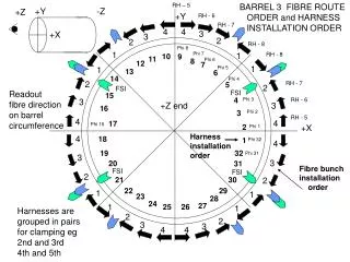
RH – 5 BARREL 3 FIBRE ROUTE ORDER and HARNESS INSTALLATION ORDER +Y -Z +Z +Y RH - 6 RH - 7 4 4 3 +X 3 2 2 RH - 8 Phi 8 1 Phi 7 1 RH - 8 10 9 11 8 Phi 6 12 7 1 Phi 5 1 13 6 14 Phi 4 2 RH - 7 5 2 FSI Readout fibre direction on barrel circumference FSI 15 4 Phi 3 RH - 6 3 +Z end 3 16 3 Phi 2 RH - 5 4 4 17 Phi 16 2 +X Phi 1 Harness installation order 4 18 1 Phi 32 4 19 32 Phi 31 3 3 20 31 Fibre bunch installation order FSI FSI 2 21 30 2 22 29 1 1 23 28 24 27 1 25 26 1 Harnesses are grouped in pairs for clamping eg 2nd and 3rd 4th and 5th 2 2 3 3 4 4
LH-1 BARREL 3 FIBRE ROUTE HARNESS INSTALLATION ORDER +Y +Z -Z +Y LH-2 LH-3 4 4 3 -X 3 +X 2 LH-4 2 Phi 8 1 Phi 7 1 LH-4 9 10 11 8 12 Phi 6 7 1 13 1 6 Phi 5 Readout fibre direction on barrel circumference Phi 4 14 LH-3 2 5 2 FSI FSI Phi 3 15 4 LH-2 3 -Z end 3 16 Phi 2 3 LH-1 4 4 17 2 +X Phi 1 Phi 16 -X Harness installation order 4 1 18 Phi 32 4 32 Phi 31 19 3 3 31 Fibre bunch installation order 20 FSI FSI 2 2 30 21 29 1 22 1 28 23 1 24 27 1 26 Harnesses are grouped in pairs for clamping eg 2nd and 3rd 4th and 5th 25 2 2 3 3 4 4
+Y -Z +Z +Y BARREL 3 DCS wire ROUTE +X Cooling DCS FSI DCS DCS wire direction on barrel circumference DCS wires are installed OVER fibres under clips FSI +Z end +X FSI FSI
+Y +Z -Z +Y BARREL 3 DCS wire ROUTE -X +X FSI DCS Cooling DCS FSI -Z end +X -X DCS wire direction on barrel circumference. DCS wires are installed OVER fibres under clips FSI FSI