SlideServe
Menu
Préférences
© SlideServe · v2026

Generating Polarized Positrons at Jefferson Lab: A Futuristic Approach

sutton avatar
1 diapositives · 131 Views · Oct 23, 2014

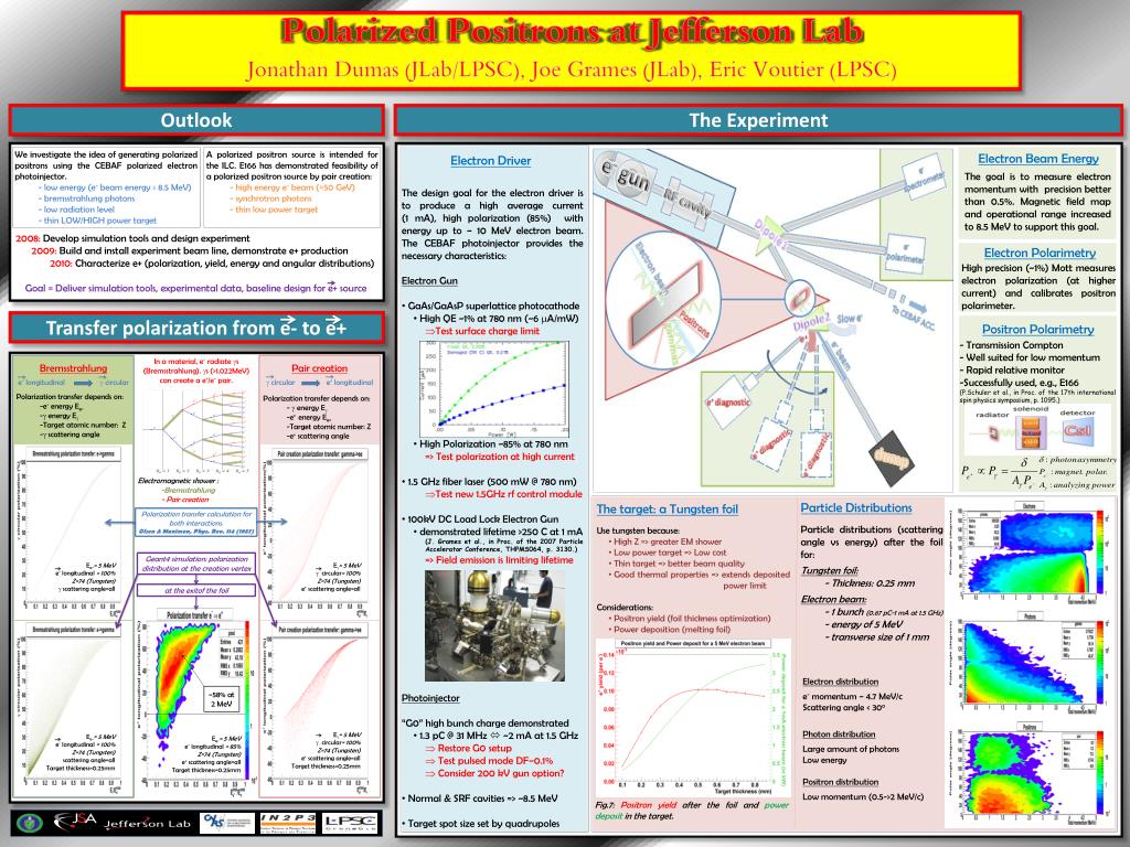
This experiment aims to create polarized positrons using a polarized electron photoinjector at Jefferson Lab. The concept involves utilizing bremsstrahlung photons and a low radiation level, thin target. The experiment targets a polarized positron source for the ILC and involves precise electron momentum measurement and high polarization electron beam generation. The setup includes a high-average-current electron driver capable of producing an 85% polarized beam. Detailed electron and positron polarimetry methods are employed to analyze the polarization transfer process. Geant4 simulations are used to study positron yield and power deposition considerations. The experiment's goal is to deliver simulation tools, experimental data, and a design for an efficient positron source.
Generating Polarized Positrons at Jefferson Lab: A Futuristic Approach - slide 1
01 / 1Generating Polarized Positrons at Jefferson Lab: A Futuristic Approach
1 / 17

Télécharger la présentation

Generating Polarized Positrons at Jefferson Lab: A Futuristic Approach
Une image / un lien ci-dessous est fourni (tel quel) pour télécharger la présentation

Politique de téléchargement : le contenu du site vous est fourni TEL QUEL pour votre information et votre usage personnel ; il ne peut être vendu, concédé sous licence ni partagé sur d’autres sites sans l’accord de son auteur.Le contenu vous est fourni TEL QUEL, pour votre information et votre usage personnel uniquement. Téléchargez la présentation en cliquant sur ce lien. Lors du téléchargement, si vous ne parvenez pas à télécharger une présentation, l’éditeur a peut-être supprimé le fichier de son serveur.Pendant le téléchargement, si vous ne parvenez pas à obtenir une présentation, le fichier a peut-être été supprimé par l’éditeur.

F I N

Plus de contenu associé

Transcription de la présentation
  1. Polarized Positrons at Jefferson Lab Jonathan Dumas (JLab/LPSC), Joe Grames (JLab), Eric Voutier(LPSC) Outlook The Experiment We investigate the idea of generating polarized positrons using the CEBAF polarized electron photoinjector. - low energy (e- beam energy ≤ 8.5 MeV) - bremsstrahlung photons - low radiation level - thin LOW/HIGH power target A polarized positron source is intended for the ILC. E166 has demonstrated feasibility of a polarized positron source by pair creation: - high energy e- beam (≈50 GeV) - synchrotron photons - thin low power target Electron Beam Energy Electron Driver The goal is to measure electron momentum with precision better than 0.5%. Magnetic field map and operational range increased to 8.5 MeV to support this goal. • The design goal for the electron driver is to produce a high average current (1 mA), high polarization (85%) with energy up to ~ 10 MeV electron beam. The CEBAF photoinjector provides the necessary characteristics: • Electron Gun • GaAs/GaAsPsuperlattice photocathode • High QE ~1% at 780 nm (~6 mA/mW) • Test surface charge limit • High Polarization ~85% at 780 nm • => Test polarization at high current • 1.5 GHz fiber laser (500 mW @ 780 nm) • Test new 1.5GHz rf control module • 100kV DC Load Lock Electron Gun • demonstrated lifetime >250 C at 1 mA • (J. Grames et al., in Proc. of the 2007 Particle Accelerator Conference, THPMS064, p. 3130.) • => Field emission is limiting lifetime • Photoinjector • “G0” high bunch charge demonstrated • 1.3 pC @ 31 MHz  ~2 mA at 1.5 GHz • Restore G0 setup • Test pulsed mode DF~0.1% • Consider 200 kV gun option? • Normal & SRF cavities => ~8.5 MeV • Target spot size set by quadrupoles 2008: Develop simulation tools and design experiment 2009: Build and install experiment beam line, demonstrate e+ production 2010: Characterize e+ (polarization, yield, energy and angular distributions) Goal = Deliver simulation tools, experimental data, baseline design for e+ source Electron Polarimetry High precision (~1%) Mott measures electron polarization (at higher current) and calibrates positron polarimeter. Transfer polarization from e- to e+ Positron Polarimetry • - Transmission Compton • - Well suited for low momentum • - Rapid relative monitor • Successfully used, e.g., E166 • (P.Schuler et al., in Proc. of the 17th international spin physics symposium, p. 1095.) In a material, e- radiate gs (Bremsstrahlung). gs (>1.022MeV) can create a e+/e- pair. Bremsstrahlung e- longitudinal g circular Pair creation g circular e+ longitudinal Polarization transfer depends on: -e- energy Ee- -g energy Eg -Target atomic number: Z -g scattering angle Polarization transfer depends on: - g energy Eg -e+ energy Ee+ -Target atomic number: Z -e+ scattering angle Electromagnetic shower : -Bremsstrahlung - Pair creation Particle Distributions Particle distributions (scattering angle vs energy) after the foil for: Tungsten foil: - Thickness: 0.25 mm Electron beam: - 1 bunch (0.67 pC-1 mA at 1.5 GHz) - energy of 5 MeV - transverse size of 1 mm The target: a Tungsten foil Polarization transfer calculation for both interactions. Olsen & Maximon, Phys. Rev. 114 (1957) • Use tungsten because: • High Z => greater EM shower • Low power target => Low cost • Thin target => better beam quality • Good thermal properties => extends deposited power limit • Considerations: • Positron yield (foil thickness optimization) • Power deposition (melting foil) Geant4 simulation: polarization distribution at the creation vertex Ee-= 5 MeV e- longitudinal = 100% Z=74 (Tungsten) g scattering angle=all Eg= 5 MeV g circular= 100% Z=74 (Tungsten) e+ scattering angle=all at the exitof the foil Electron distribution e- momentum ~ 4.7 MeV/c Scattering angle < 30o Photon distribution Large amount of photons Low energy Positron distribution Low momentum (0.5->2 MeV/c) ~58% at 2 MeV Eg= 5 MeV g circular= 100% Z=74 (Tungsten) e+ scattering angle=all Target thickness=0.25mm Ee-= 5 MeV e- longitudinal = 100% Z=74 (Tungsten) scattering angle=all Target thickness=0.25mm Ee-= 5 MeV e- longitudinal = 85% Z=74 (Tungsten) e+ scattering angle=all Target thickness=0.25mm Fig.7: Positron yield after the foil and power deposit in the target.