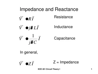
Inductive Reactance
Inductive Reactance. Electronics. Inductors in AC Circuits. Inductance. I nductance opposes a change in current. Inductors create a voltage that opposes the current. Counter EMF (voltage). v. L. Inductance. The Henry (symbol: H) is the SI unit of inductance .

Inductive Reactance
E N D
Presentation Transcript
Inductive Reactance Electronics
Inductance • Inductance opposes a change in current. • Inductors create a voltage that opposes the current. • Counter EMF(voltage) v L
Inductance • The Henry (symbol: H) is the SI unit of inductance. • It is named after the American physicist Joseph Henry..
Current Voltage Capacitor in DC
E L I Voltage Inductance Current Voltage leads Current in an Inductive Circuit
Current Voltage Inductance in AC
Voltage Current I = Ipsin(2πft) V = L di/dt Ip-Peak Current V = L d(Ipsin(2πft))/dt 2π-Cycle f-frequency(Hz) V = L Ip(2πf)cos(2πft) t-time(seconds) Vp = Ip(2πf)L
Vp = Ip2πfL Vp/Ip= 2πfL R = 2πfL Inductive Reactance XL = 2πfL L is an Active Component
Calculate the maximum current in a coil which has an inductance of 3 mH. The frequency is 60Hz. The maximum voltage across the coil is 6 V. E=6V L=3mH f=60Hz XL = 2πfL I = E/XL XL = 2π(60Hz)(.003H) I = 6V/1.13Ω XL = 1.13Ω I = 5.3A
Inductive/Resistive Circuit • 90° Phase Shift caused by Inductor • Impedance, Z, is calculated by adding XL and R vectorially. XL Z R
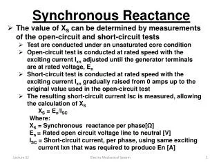
What is the impedance of a 100mH choke in series with a 470Ω resistor with a 12V, 60Hz applied across them? What is the phase angle between voltage and current? L=100mH f=60Hz R=470Ω E=12V XL = 2πfL XL = 2π(60Hz)(.1H) XL = 37.7Ω
Z XL R
Current Voltage 4.6° Inductance in AC
Capacitor Values • 1mF = 1 X 10⁻³F • 1μF = 1 X 10⁻⁶F • 1nF = 1 X 10⁻⁹F • 1pF = 1 X 10-12F
RLC Circuits • 90° Phase Shift caused by Inductor • -90° Phase Shift caused by Capacitor Z XC XL R
Xc = 1/(2πfC) XL = 2πfL Xc = 1/(2π(60)(1.5X10-6) XL = 2π(60)(0.65) Xc = 1768Ω XL = 245Ω Z XC XL 𝚹 = -81° ICE – Current leads Voltage by 81° R
Resonance • The frequency where XL = XC • The Circuit becomes a purely resistive circuit Xc = 1/(2πfC) XL = 2πfL Xc = XL 1/(2πfC) = 2πfL 1/(4π2CL) = f2 = f
= f 161 Hz= f
Worksheet Lab 2-6 Capacitors In AC Circuits Problems
Reactance Test Classwork • Lab 7, Book 2 – Capacitive Reactance • Worksheets • Lab 2-5 • Lab 2-6 • Lab 2-8 • Lab 2-9 • Lab 2-11 • Lab 2-12 • Lab 2-13 } Due the day of the test!!