Download
1 / 30
300 likes | 318 Vues
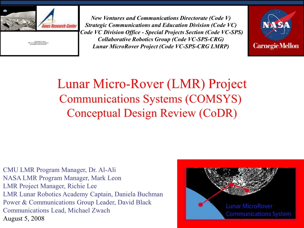
This document outlines the communications system for the Lunar Micro-Rover (LMR) project. It includes the technology challenge, systems requirements, and metrics for transmitting data and video in real-time from the rover to the Earth.

E N D
New Ventures and Communications Directorate (Code V)Strategic Communications and Education Division (Code VC) Code VC Division Office - Special Projects Section (Code VC-SPS) Collaborative Robotics Group (Code VC-SPS-CRG)Lunar MicroRover Project (Code VC-SPS-CRG LMRP) Lunar Micro-Rover (LMR) ProjectCommunications Systems (COMSYS) Conceptual Design Review (CoDR) CMU LMR Program Manager, Dr. Al-AliNASA LMR Program Manager, Mark LeonLMR Project Manager, Richie LeeLMR Lunar Robotics Academy Captain, Daniela BuchmanPower & Communications Group Leader, David BlackCommunications Lead, Michael ZwachAugust 5, 2008
Section 0Communications System Outline Communications System (COMSYS) Description Technology Challange Systems Requirement Document Conceptual Design (CoD) Cost Schedule Probability of Success A. Appendix: Student White Papers
DSN LML ARC RMOC LMR NISN Section 1Communications Systems Definition and Description 1.1 Communications System Description The System is physically composed of the following components for the communication process : the antenna, radio hardware, receiving ground stations, NASA’s secure International IP Network, as well as test and analysis nodes. 1.2 Communications System Definition The LMR communications system is composed of two major communication networks, two spacecraft communication subsystems and one rover operations center: 1.2.1 Rover Mission Operations Center (RMOC) @ ARC 1.2.2 NASA Integrated Science Network (NISN) @ MSFC 1.2.3 Deep Space Network (DSN) @ Canberra, White Sands and Madrid 1.2.4 Lunar Micro Lander (LML) communication subsystem @ Luna 1.2.5 Lunar Micro Rover (LMR) communications subsystem @ Luna
Section 2TechnologyChallenge Communications Systems 2.1 Technology Challenge- Communications System To transmit 120 Kbps over a 10 Watt signal carrying a real-time video transmission. Minimizing latency to tele-operate from the Earth at 10% the traditional cost. Note that using an omni-directional antenna and a 34 meter antenna network will only guarantee a 38.4Kbps data rate. Data rate issues could easily be resolved by increasing cost, however latency can not be decreased beyond a specific minimum due to physical limitations of light speed. 2.1.1 Data Rate > 100Kbps over UDP/IP 2.1.2 Latency < 4.5 Seconds 2.1.3 Cost = 1/10 legacy cost
Section 3LMR Systems Requirement Document (SRD)Communications Systems Section 3.1 Fundamental Data Requirements (LMR & LML) 3.1.1 RAM and ROM Data Storage 3.2 Communications Systems Power Requirements (LMR & LML) 3.3.1 COMSYS Space Transit Power Requirement 3.3.2 COMSYS Lunar Pre-Deployment Power Requirement 3.3.3 COMSYS LMR Surface Mission Power Requirement 3.2 Mass & Size Limitations (LMR & LML) 3.3 Cost Limitations (LMR & LML) 3.4 Flight Qualification and Certification Testing Requirements 3.5 COMSYS Subsystems Requirements 3.6 Required Probability of Success 3.7 COMSYS Failure Communication Requirements
Power & Mass required to Implement Primary Config. Section 3Systems Requirements Document • Description Weight Power Required • LMR Dedicated S-Band Radio 0 grams 64.0 Watts • S-Band Variable Phased Array 7 grams 0.0 Watts • Microhard UHF Modem 120 grams 2.0 Watts • Additional Wiring Harness 20 grams 0.1 Watt • S-Band Radio to UHF-Band Radio Link 1 gram 0.0 Watt • Omnidirectional UHF Antennae 35 grams 0.0 Watt • Modem Mounting 10 grams 0.1 Watt • RS-422 Com port to CPU 5____ grams 0.1 Watt • TOTAL 198 grams 66.3 Watts • Replaces omnidirectional Antennae • ** Burden Presumes and existing 5 Watt radio on board Lander
Section 3Systems Requirements Document: COMSYSMass and Volume Requirements for LMR & LML LMR • Components: • UHF Radio • UHF antennae • UHF-band RF cables • Power cables • RS-232 data cables • Mass: 199 gm • Volume: 0.249 M³ LML • Components: • S-Band Radio • S-Band Antennae • S-band RF cables • UHF-band Radio • UHF-band antennae, • UHF-band RF cables • RS-232 data cables • power cables • Mass: 699 gm • Volume: 0.749 M³ LML & LMR Total • Total Mass: 898 gm • Total Volume: 0.998 M³
Section 3Systems Requirements DocumentData Communication Requirements S-Band Downlink Data Rate with 3 dB Margin: 60 Kbps S-Band Downlink Data Margin with 0 dB Margin: 120 Kbps Uplink Data Rate: 8 Kbps UHF-Band Relay link LML Downlink Data Rate: 120 Kbps Data Latency: 5 seconds LMR-Relay to RMOC Bit Error Rate 1x10⁵bit errors per second Data Link MTTF: MTTF > 3 hours. Data Protocol: UDP/IP & TCP/IP Interplanetary Communication Frequency: S-Band Lunar Surface-to-Surface Communication Frequency: UHF-Band Uplink Communication Network: Deep Space Network (DSN) Uplink Antennae Array DSN 34M tracking antennae array UHF-Band Link Input Power: ~7 Watts UHF-Band Link Output Power: ~1 Watt S-Band Link Input Power: ~ 70 Watts S-Band Link Output Power: 10 Watts
Section 3Systems Requirements DocumentMetrics • Effectiveness Metric: (1.0) • Actual Data Rate / Design Data Rate • = maximum120Kbps / target60Kbps • = 200 % maximum value • Probability of System Success Metric: Must be greater than (50%) • (LMR Subsystem)*(LML Subsystem) *(LMR POWSYS)*(LML POWSYS)= • (.95)*(.85)*(.80)*(.90)=%58 • Total Probability=58% • Probability is greater than or equal to 100% =(1.0) • Data Link Reliability : (1/1x10⁵ errors/sec) • Based on the Bit Error Rate • Data Link Maintainability : (90%) • Mean Time To Failure (MTTF) ( > or = ) Time System is up before com loss.
Section 3Systems Requirements DocumentS-Band Radio Subsystem Requirements • 10 Watt Downlink S-Band Radio • Input Voltage: 15 –50Vdc continuous operation • Operating Temperature: -20°C to +60°C • Vibration: 14.1 grams (qualification level) • Radiation Tolerance: 10k Rads(Si) -box level (higher with shielding) • Latch-up: Detection and Mitigation (2μsec response, 200msec reset) • RF Input Amplitude Dynamic Range: -130dBm to -40dBm • RX Carrier Tracking range: ±105kHz • RX Carrier Acquisition Threshold: -119dBm • RX Noise Figure: 4dB • RX Carrier Acquisition Time: <0.5sec • TX Frequency Stability: ±20ppm over temperature range • Output Power: Adjustable in 1dB steps from 0.5W to 5W • Output Protection: No damage; open or short circuit • Ranging: B/W: 100Hz to 1MHz (-3dB) Turnaround UMI: 1:1 (±10%) • Uplink Modulation Index: 0.3Rad peak (nom.)
Section 3Systems Requirements DocumentS-Band Radio Configuration Requirements • 10 Watt Downlink S-Band RadioConfiguration • S-Band Tuned to DSN & TDRS Frequencies • RS-422 serial data interface • Uplink from Earth 8kbps • Downlink to Earth at rate of 120Kbps • 3 modules; each 3.5 x 2 x 1 inches • (RX,TX,HPA & interface/power) • Mass: < 200g per module • Total Mass < 800g • Receiver power: < 1 Watt • Transmit (10.0Wrf): < 64 Watts
Section 3Systems Requirements DocumentUHF Radio Requirements Potential Match: Microhard Model # 921-OEM
Section 4Conceptual Design 4.1 Communicating Conceptual Design (CoD) Photos of prototypes, graphical data, cadcam files or an artists’ conception of the system’s final physical appearance. Based on proposed technologies, methods and substantiated theories believed capable of executing the system. 4.2 Block Diagram of ETE LMR Communication Systems 4.3 Block Diagram of LMR Systems 4.4 Block Diagram of LMR Subsystems 4.5 Electrical Schematics (where appropriate) 4.6 Communications Schematics (where appropriate) 4.7 SW Decision Flow Chart (where appropriate) 4.8 Component schematics and physical layout of COTS used and or modified for this mission. 4.9 General Engineering & Calculations
Section 4Integrated LMR Communication SystemBlock Diagram ARC Rover Operations Center Lunar Lander Lunar Microrover 4.2 Communication System is composed of one operations center, two international communications networks, and two Lunar communication subsystems. NASA Integrated Science Network Deep Space Network 34M NISN Fiber Optics Fiber Optics S-Band UHF-Band
Section 4:Integrated LMR Communication System Terrestrial Network: RMOC/NISN/DSN NISN N254 NASA Integrated Services Network (NISN) DSN Goldstone Tracking Facility Barstow, CA Rover Mission Operation Center (RMOC) Dedicated Digital Service Dedicated Digital Service Serial Interface ARC-RMOC Mt. View, CA
Section 4:LMR Communication System Deep Space Network (DSN) 34M 34 Meter Antennae Downlink Fiber Optics to ARC RMOC Uplink Planetary Coverage
Uplink/downlink with Earth/DSN Section 4:Conceptual DesignLML& LMR Subsystems Lander Rover
Serial Interface Card Section 4:Conceptual DesignLMR Subsystems Lunar Microrover Computer System (900-928 Mhz) Primary Radio System CPU RS 422 Serial Interface ATA Bus UHF-Band Omnidirectional Antennae CMX Connectors UHF-Band Radio ** Hopping Modulation Db-9 Connectors Peripherals
Computer System Serial Interface Card ATA Bus Microrover Communication Relay Link RS-422 Serial Interface Lander CPU UHF-Band Omnidirectional Antennae UHF-Band UHF-Band Radio ** .1-1 Watt Link RF Cable with SMA Connectors Db-9 Connectors Section 4:Conceptual DesignLMR Subsystems Required Modification to Lander to support MicroRover Communication Relay * Specifications currently met by Aeroastro product ** Specifications currently met by Microhard product
Needs Work Section 4:Conceptual DesignS-Band DownLink Calculations
Section 4:Conceptual DesignModulation and Coding S-Band radio data framing structure CCSDS AOS at top level 6 byte header packet structure Encoding (executed in software) rate ½ convolutional code (CC) with Reed Solomon (RS) Decoding (executed at ground station) For rates under 20Mbps it may be possible to use a computer real time Modulation BPSK (modulated directly onto the carrier) If necessary QPSK is also possible but is a second choice (See System Testing with TDRSS)
Section 4:Conceptual DesignS-Band Radio Testing Series A Test (Radio Standalone TDRSS Test) Generate End to End Simulation of Rover loaded on to a PC. Travel to S-Band Manufacturing site and connect to radio over RS-232 to simulation and uplink to TDRSS. Calculate data rates using uplink with a 5-watt radio Test omni directional antennae Test Evolved Antennae Series B Test (Integrated Rover TDRSS Test) Test radio on low look angle using TDRSS Obtain location on CONUS which will force us to use TDRSS from a low look angel much like we will from the moon to DSN Travel to location and test radio by transmitting from a low look angle to TDRSS.(This will produce similar dynamics with the antenna performance) Compare and contract evolved antennae and omni directional antenna
Section 4Conceptual DesignIntegrating into a Lunar Lander Payload The following actions should be taken for successful integration with LMR’s Communication System: Potential Modifications to the Lander CPU ports to support a RS-422 serial interface connecting the rovers’ UHF Radio. (REQUIRED) Potential Modifications to the Lander’s Data Routing System to include directing data Relays between the LMR and the LML during rover surface deployment. (REQUIRED) These actions are assumed: Modifications to the Lander to secure LMR for Space Flight. Modifications to the Lander’s electrical infrastructure to provide umbilical power connection during space flight. Formal Designation as a Lunar Lander payload.
Section 4 Conceptual DesignIntegrating into a Lunar Lander Payload Impact to Lunar Lander Weight (7.5Kg) Rover (1.2 Kg) Communication Relay (1.3 Kg) Securing Assembly & Misc. connectors (+ 10Kg ) Total Volume (- 2.1 Cubic Meters) Power (- 15 Watts) Power during space flight (transit time 3 days?) ~ 1.3 MJoules (- 35 Watts) during Rover Surface Deployment (3 hr.) ~ 378 KJoules (- 35 Watts) 12 days after landing (1hr.)*~ 126 Kjoules ~ 1.8 MJoules CPU (90% of available cycles) during deployment (+1 RS-422 Serial Ports) Attached to CPU
Section 4:Integrating into a Lunar Lander Payload LMR should be treated like an onboard payload and thus realize the following benefits: Active Mission time is doubled from 30 minutes to 60 minutes Theoretical Mission time is extended from 1 hr. to 2hr. Communication system success achieves a probability of 100%. Other Benefits include: Backup communications capability for Lunar Lander Effective use of excess power generated by Landers Solar panels.
Section 4:Conceptual DesignCommand and Telemetry CCSD Frame Structure * * (CCSDS) Consultative Committee for Space Data Systems
Section 5:Cost 5.1 Cost by Deliverable Product 5.1.1 Prototype LMR Communication System integrated into LMR-P5 5.1.2 Flight Developed LMR Communication System integrated into LMR-Alpha 5.1.3 Flight Qualified LMR Communication System integrated into LMR-Beta 5.1.4 Flight Certified LMR Communication System integrated into LMR-1 5.1.5 Flight Certified LMR Communication System integrated into LMR-2 5.2 Cost by Resource Category 5.2.1 Labor Cost (Civil Service, Contractor, Subcontractor, Volunteer) 5.2.2 Facilities Cost (Leased, Constructed, Facilities provided at no cost to the project must still be estimated for full cost accounting) 5.2.3 Laboratory Equipment Cost 5.2.4 System Fabrication Cost (NASA Service Pools, contracted Non-NASA Machine shops 5.2.5 COTS Modifications, Hardware, Firmware, Software and Materials Cost 5.2.6 Flight Qualification and Certification Cost 5.2.7 Travel (Government & Contract) Cost 5.2.8 Configuration Management Cost
Section 7:Probability of SuccessMetrics • Effectiveness Metric: (1.0) • Actual Data Rate / Design Data Rate • = maximum120Kbps / target60Kbps • = 2.0 maximum value • Probability of System Success Metric: (50%) • Primary Configuration Probability (PCP) of success= • (UHF Radio & Antennae)*(LMR Power)*(LMR CPU)*(Lander Relay)*(Assorted connections)= • (.95)*(.95)*(.90)*(.85)*(.85)=%59 • Secondary Configuration Probability (SCP) of success= • (S-Band Radio & Antennae)*(LMR Power)*(LMR CPU)*(Assorted connections)= • (.95)*(.95)*(.90)*(.85)=%69 • Total Probability=PCP+SCP=118% • Probability is greater than or equal to 100% =(1.0) • Data Link Reliability : (1/1x10⁵ errors/sec) • Based on the Bit Error Rate • Data Link Maintainability : (90%) • Mean Time To Failure (MTTF) = Time System is up before com loss. No data so assume 30 minutes. * • Mean Time To Repair (MTTR) = Time required to reestablish Communication following link loss. • Failure of Primary system initiates Secondary system in about 4 minutes. • MTTR = 4/60 =1/15= 6.7% * Note: No Data on MTTF, Probability of UHF system failure or UHF signal loss due to physical attenuation