Download
1 / 27
280 likes | 414 Vues
This document outlines thermal control measures to suppress seeing caused by temperature differences in enclosure surfaces. Implementing strategies such as passive interior flushing and maintaining optimal surface and air temperature differentials is crucial. The performance analysis includes requirements for skin temperature subcooling and ventilation flow rates to minimize optical distortion. Methods of cooling, including air and water systems, are examined, with specific operational limits and energy requirements detailed to enhance observational quality and reduce thermal-induced seeing.

E N D
Enclosure Thermal Control 25 August 2003 ATST CoDR Dr. Nathan Dalrymple Air Force Research Laboratory Space Vehicles Directorate
Enclosure Thermal Control • Function: Suppress seeing Seeing is caused by temperature differences If a surface is the same temperature as the surrounding air, that surface introduces no seeing
Requirements • Suppress enclosure seeing • Racine experiment: q = 0.15 (Ti - Te) 1.2 • Ford analysis: q = 0.012 (Ts - Te)1.2 • IR HB aerodynamic analysis: q = q(DT, V, l) • Bottom line: requirements on surface-air DT, interior-exterior DT, and wind flushing • Provide passive interior flushing to equalize interior and exterior temperatures and to suppress structure and mirror seeing Ref: Racine, Rene, “Mirror, dome, and natural seeing at CFHT,” PASP, v. 103, p. 1020, 1991.
Layer thickness Given layer thickness and DT, we can estimate q. Wavefront variance Fluctuating density Line-of-sight correlation length Gladstone-Dale parameter Surface-air temperature difference Phase variance Strong/weak cutoff ~ 2 rad Blur angle IR Handbook Seeing Analysis Ref: Gilbert, Keith G., Otten, L. John, Rose, William C., “Aerodynamic Effects” in The Infrared and Electro-Optical Systems Handbook, v. 2, Frederick G. Smith, Ed., SPIE Optical Engineering Press, 1993.
Hydrodynamic term Buoyancy term IR Handbook Seeing Analysis (cont.) Layer thickness (mks units): L: upstream heated length (m) DT: average temperature difference over upstream length (˚C) V: wind speed (m/s) Assume: If DT < 0 then buoyancy term does not contribute to layer thickness.
Shell Seeing, Diffraction-Limited Error Budget Blue contours: rms wavefront error (nm) l = 500 nm Acceptable operating range, assuming no AO correction. AO correction will extend the “green” area.
Shell Seeing, Seeing-Limited Error Budget Blue contours: 50% encircled energy (arcsec) l = 1600 nm Acceptable operating range
Shell Seeing, Coronal Error Budget Blue contours: 50% encircled energy (arcsec) l = 1000 nm Acceptable operating range
Dome Seeing (Inside/Outside Air DT) Correlation by Racine (1991) Approximate error budget Need lots of passive flushing! Approximate DT requirement Ref: Racine, Rene, “Mirror, dome, and natural seeing at CFHT,” PASP, v. 103, p. 1020, 1991.
Good seeing from KE test BBSO Dome Seeing Experiments IR Handbook aerodynamic treatment Correlation of Racine (1991) IR Handbook aerodynamic treatment Ref: Racine, Rene, “Mirror, dome, and natural seeing at CFHT,” PASP, v. 103, p. 1020, 1991.
Bad seeing from KE test BBSO Dome Seeing Experiments
A Nighttime Comparison: Gemini Dome Acceptable seeing observed with shell subcooled by 3 ˚C. DT = -3 ˚C 1 Duct exhaust fan on, low-moderate wind (3 - 5 m/s)
Bottom Line Requirements • Enclosure skin temperature needs to be subcooled by up to 3 ˚C • Interior air temperature needs to be within 0.5 ˚C of ambient outside air • Need large passive flowrate to flush interior
Skin Energy Balance [~0 W/m2] [377 W/m2] [374 W/m2] [98 W/m2] [~100 W/m2] Quantities vary by location on dome and weather conditions We want to use this term to control the skin temperature
Skin Thermal Control System Concept • Concept Features: • White oxide paint • Large e • Small as • Chilled skin • Air • Liquid (EGW) • Insulationprevents interior from beingchilled by skin coolant
Skin Thermal Control System Concept (cont.) Oblique skin panels: air cooled, h ~ 5 W/m2-K Shutter: air cooled, optional water cooling on lower end hair ~ 8 W/m2-K hH2O ~ 100 W/m2-K Option: use fins on skin underside to increase effective area Enclosure support wall: water cooled if presenthH2O ~ 100 W/m2-K Sun-facing skin panels: air or water cooled hair ~ 5 W/m2-K hH2O ~ 100 W/m2-K
Skin Cooling System Flow Loop Insert diagram here
MuSES Modeling: Validation at Gemini North Validation
Skin Thermal Control System Performance Surfaces that see cold sky subcool MuSES snapshot at 1430LT, 30 April 2003, Mauna Kea Wind speed = 0.5 m/s Ambient air Te = 7 – 8 ˚C Air Cooling Only on SkinESW Water Cooled Most of surface is acceptable Sun-facing areasare ~ 5 ˚C hotter than ambient
Skin Thermal Control System Performance (cont.) Surfaces that see cold sky subcool MuSES snapshot at 1430LT, 30 April 2003, Mauna Kea Wind speed = 0.5 m/s Ambient air Te = 7 – 8 ˚C Air & Water Cooling Nearly all of surface is acceptably cool Sun-facing areascooled with water
Cooling Requirements • At peak heat load, surface cooling requires: • Air-cooled skin: 56 kW • Water-cooled skin: 18 kW • Lower shutter: 14 kW • Air-cooled shutter: 18 kW • Total for carousel: 106 kW • Enclosure support wall: 104 kW • Grand total: 210 kW (60 tons) • Next steps: • Fan and system curves • Heat exchanger specs • Chiller specs • Time response of fluid volume
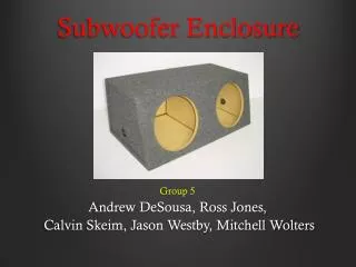
Flushing System Concept 168 m2 flow area,each side 42 vent gates
Active Interior Ventilation • Gemini volume flowrate: 10 enclosure volumes/hour (150,000 m3/hr) • This flowrate on the smaller hybrid gives V ~ 0.2 m/s average • Directed flow can give V~0.5 – 1 m/s over much of structure Fans may be mounted remotely or on carousel
Active Ventilation Issues • Fan blades heat air seeing • Require homogenizing screens, cooling coils downstream of fans • May not be simple to mount all this on carousel possible to mount remotely
Shell Seeing Performance Blue contours: rms wavefront error (nm) Red: average DT of skin, front skin, shutter, lower shutter, ESW Most of the dome surface will give acceptable seeing Back of shutter subcools. May need to add water cooling there as well.