Thermal Control
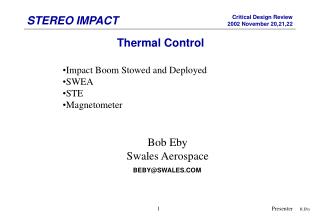
Thermal Control. Impact Boom Stowed and Deployed SWEA STE Magnetometer. Bob Eby Swales Aerospace. BEBY@SWALES.COM. R.Eby. IMPACT BOOM STOWED. Housing for boom & release mechanism covered with MLI Conductively isolated from S/C, R= 25 C/W

Thermal Control
E N D
Presentation Transcript
Thermal Control • Impact Boom Stowed and Deployed • SWEA • STE • Magnetometer Bob Eby Swales Aerospace BEBY@SWALES.COM Presenter R.Eby
IMPACT BOOM STOWED • Housing for boom & release mechanism covered with MLI • Conductively isolated from S/C, R= 25 C/W • Exposed instruments (STE, SWEA, & Mag ) are insulated and have small heaters, but 41 sq.cm opening remains at end. • Hot case (Delta V), 45 degrees to sun, average temp = 16 C • Cold case, in absence of heater power: • Temp of sun lit end = -65 C • Opposite end =--70 C • At deployment, 5 watt heater is required to maintain 0 C. Presenter R Eby
IMPACT BOOM DEPLOYED • Four telescopic Carbon Epoxy sections • Poor heat transfer between sections • Completely shadowed by S/C during fine pointing • Even if ends are maintained at 20 C, temp decreases rapidly to –230 C Presenter R. Eby
IMPACT BOOM DEPLOYED CONT’D • Potential solutions analyzed: • Internal heaters • Radiant heater at S/C end • Solar collector fins • Solution: • Use Solar Collector Fins 25 sq cm ea. • Test Transition joints Solar Collector Fin Presenter R. Eby
SWEA • Temp limits: • Operating -25 to 30 C • Non operating –30 to 50 C • Bias cold – Dissipation is only 0.55 watts. Use thermostatically controlled heater. • SWEA support structure and analyzer grids provide major heat transport paths. • Radiation is curtailed by gold plated reflectors. • Effective emittance of grid is area weighted; grid is 90 % open. • At lower design limit, –25 C, radiation heat transfer through grid is small. Presenter R.Eby
SWEA THERMAL DESKTOP MODEL Presenter R.Eby
PEDESTAL BOARDS Analysis must be integrated with pedestal boards which dissipate an additional 0.94 watts. Presenter R. Eby
SWEA CONT’D • .Pedestal Boards • Two shield boards will be black anodized to enhance radiation heat transfer. • Radiation areas are large relative to heat dissipation. • Heat transfer is provided by SWEA and pedestal walls to grid openings and IMPACT boom. • Loss through MLI is significant. (Effective emittance: 0.01 to 0.03) • Multi-node model in Thermal Desktop generated to evaluate heater power requirements • Use thermostatically controlled heater 1.5 watts ( 75 % duty cycle) • Survival: 2.75 watts to maintain –20 C (100 % duty cycle at 25 volts). • Hot case ( 45 deg to sun, unit off): Max deflector temp = 165 C, sensor at 16 C. Presenter R.Eby
RESULTS OF INTEGRATED THERMAL MODEL Presenter R.Eby
STE INSTRUMENT Presenter R.Eby
STE-U SHIELD Sun Shield and sun facing side of STE are covered with MLI, silver Teflon cover. Presenter R.Eby
STE D & U • Temperature Limits: -140 to 40 C • Internal dissipation = 0.04 watts • Thermal coatings must be electrically conductive. • Design Objective: “Make as cold as possible”. • Use MLI to protect vulnerable surfaces during Delta V maneuvers. • STE-D: Top and sides are black radiators – cover bottom with MLI • STE-U: Sides and bottom are black radiators – cover top of unit and sun shield with MLI • Radiator area for both units is 65 sq cm (10 sq.inches); small areas are sunlit during off-nominal cases. • Instruments are conductively isolated from pedestal using Vespel isolators: conductance = 0.005 w/C. • During fine-pointing, • STE-D detector is maintained below –70 C’ • STE-U detector is maintained below –70 C • Survival power is not required. Presenter R.Eby
STE D & U OFF-NOMINAL CASES DELTA V maneuvers -S/C at 45 degrees off pointing for up to 105 minutes. -Instrument power turned off. -Detector temperatures will be maintained below 0 C. EARTH ACQUISITION (Safe hold) -Sun integrated over sides during time period. • Transient hot case shows temperature rise of 70 C in 0.2 hours. • Mass of STE =28 grams • Absorbtivity = 0.91 SURVIVAL COLD CASE -Use 50 % of Vespel conductance. -Steady state detector temperature = -90 C. Presenter R.Eby
MAGNETOMETER • Temperature Limits • Operating: -20 to 45 C • Survival: –30 to 50 C • Normally in sun – Cover all six sides of Magnetometer with 22 sheets MLI – outer cover sheet Silver Teflon ITO, effective emittance =0.03 • Bias cool. Use small heater. (Mag dissipation is zero.) • Instrument is supported off of IMPACT boom by plastic (PEEK) tray, Thermal conductance between Mag and tray is less than 0.0042 W/C • A one watt thermostatically controlled heater (75 % duty cycle) provides temperature control during normal operation. When unit is completely shadowed, duty cycle is less than 95 %. Presenter R.Eby
THERMAL COATINGS Presenter R.Eby
IMPACT STOWED REDUCED TSS MODEL Presenter R.Eby
IMPACT DEPLOYED REDUCED TSS MODEL Presenter R.Eby