Structures and Thermal Control
Learn about structures, loads, mechanics of materials, material selection, and thermal control in aerospace engineering for spacecraft design and launch. Understand the importance of strength, stiffness, and stability in space vehicle structures.

Structures and Thermal Control
E N D
Presentation Transcript
Structures and Thermal Control Dr Andrew Ketsdever MAE 5595 Lesson 12
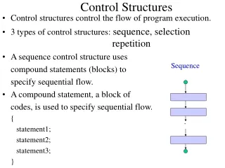
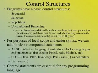
Outline • Structures and Mechanisms • Introduction • Structural Loads • Static • Dynamic • Mechanics of Materials • Material Selection • Launch • Structural Design • Thermal Control • Introduction • Thermal Loads • Design • Passive • Active
Structures and MechanismsIntroduction • Structures • Mechanically supports all other subsystems • Provides load path and distribution • Attaches spacecraft to the launch vehicle • Isolation and vibration damping • Provides for separation from the launch vehicle • Provides shielding for components • MMOD, Radiation, AO • Satisfy all strength and stiffness requirements • Primary structure • Carries spacecraft’s major loads • Secondary structure • Support of wires, propellant feed lines, etc. • Brackets
Structures and MechanismsIntroduction • Mechanisms • Two applications • High cycle • Antenna gimbals • Solar array drives • Reaction wheels • Low cycle • Gravity gradient boom • Solar array or antenna deployment • Contamination cover removal
Structural Loads • Static (constant with time) • External • Weight of supported components during integration • Internal • Pressurized tanks • Mechanical preloads • Thermoelastic loads • Dynamic (time varying) • External • Transport to launch site • Launch vehicle • Acoustic loads • Wind gusts • Attitude control actuators • Internal • Thermal cycling • Mechanism operation
Mechanics of Materials • The 3 over-riding design criteria for space vehicle structures are: • Strength: ability to support a static load • Stiffness (Rigidity): measure of flexibility (need to avoid L/V natural frequencies) • Stability (Buckling): resistance to collapse under compression • For simplicity, we will consider only spacecraft that resemble beams
Strength Strain: Young’s Modulus: Stress: Poisson’s Ratio:
Natural frequency is the frequency at which an unforced, vibrating system will vibrate When vibrating freely, a single degree of freedom system will always vibrate at the same frequency, regardless of amplitude Stiffness
Without energy dissapation, harmonic motion will go on forever. Of course, things do quit vibrating eventually. A damping force is one that resists vibration and dissipates energy, normally through heat (friction). A viscous damping force is proportional to velocity; we typically assume viscous damping to simplify analysis. Assuming a spring is linear-elastic, Stiffness
Theoretically, a linear-elastic column will buckle at a critical, or Euler Buckling Load, Pcr, given by This equation applies only if the axial stress at buckling (Pcr/A) does not exceed the materials proportional limit. Otherwise, replace E with Et, the tangent modulus which is the slope of the stress/strain curve at the operating stress level (the buckling stress in this case). Stability
Cyclic Failure • Fatigue failure is caused by repeated, cyclical loading of a component at a load well below ultimate or yield It is difficult (or impossible) to accurately predict the actual fatigue limit for a given part. The only sure way is to test to failure. s Fatigue limit n-cycles
Mechanics of Materials • Flexibility • Measure of how much a structure deflects under a load • Stiffness (Rigidity) • Inverse of flexibility • Below Elastic Limit • Material returns to initial length after stress removed • Material becomes plastic above the elastic limit • Material yields and has residual strain • Materials • Ductile • Yields substantially without failing • Brittle • Yields without much deformation
b Tension h Neutral axis Neutral axis Compression Mechanics of Materials Cantilever Beam in tension P tension x Cantilever Beam in bending M=Px P c Neutral axis x Moment
Neutral axis Tension Compression Mechanics of Materials P1 Satellite P2 x LV interface
Mechanics of Materials Shear Strain: G = shear modulus t
Structural Design • Design Stress x Factor Safety < Allowable Stress • Allowable Stress depends on • Type of stress • Material used
Material Selection Adapted from Sarafin, Spacecraft Structures and Mechanisms, 1998.
Launch Profile • Launch • S-IC Inboard Engine Cut Off • S-IC Outboard Engine Cut Off • S-II Ignition • S-II O/F Mixture Change (lower F) • S-II Shut Down • S-IVB Ignition (one J2 engine) • S-IVB Shut Down
Launch • Axial and Lateral Loads • Acceleration due to thrust • Typically increases with time due to launch vehicle mass reduction • Can be several to tens of g’s • Vibration • Random vibe • Shock (burst) • Liftoff • Staging • Acoustic • Sound pressure waves
LV Interface: Shock Ring • Needed a design to provide axial and lateral isolation to satellite payloads • Variation of axial shock ring • Increases the path the shock has to travel while providing parallel damping • All metallic load path • Aluminum construction for light payloads • Titanium for larger payloads • Easily manufactured and assembled • Integrates in a stacked configuration • Viscoelastic constrained layer damping on outer and/or inner circumference
Flexible Body Dynamics • Finite Element Method • Used to predict structural modes, natural frequencies, and responses to applied loads • Models of the structure with discrete degrees of freedom • Break a complex structure into simple structures that are easy to analyze • Matrix math M1 Payload k1 M2 Oxidizer k2 M3 Fuel F(t)
Launch Vehicle LoadsPower Spectral Density (PSD) Mean Square Accel. (g2) Power Spectral Density (g2/Hz) Cumulative Mean-square acceleration PSD Frequency (Hz) At a given frequency, the PSD is the slope of the function of cumulative mean square acceleration. The area under the acceleration PSD curve is equal to the overall mean square acceleration. Thus, the the overall root-mean-square value equals the square root of the area under the PSD curve.
Launch Vehicle LoadsUsing a PSD curve • Given a PSD for a LV, for example, we’d like to know the acceleration experienced by our spacecraft • Miles’ Equation tells us this ..
Secondary structures: • appendage booms • support trusses • platforms • solar panels • antenna dishes • Primary structures: • body structure • launch vehicle adapter • Tertiary structures: • brackets • electronics boxes SSAM: Fig. 1.1 Structural Design • Structural components are categorized by the different types of requirements, environments, and methods of verification that drive their design • Primary structures are usually designed to survive steady-state accelerations and transient loading during launch and for stiffness • Designs of secondary and tertiary structures tend to be driven by stiffness, positional stability, and fatigue life
Structural Requirements • Manufacture & Assembly (handling fixtures) • Transport & Handling (cranes, dollies, transport to launch site) • Testing (vibration, acoustic) • Pre-launch (stacking and preflight checks) • Launch • Steady state acceleration • (typical max acceleration 6 g’s axial, 3 g’s lateral) • Vibration and acoustic noise • Shock from staging and separation • Mission Operations (thrusters, attitude maneuvers) • Very benign compared to launch and testing • Reentry
StructuresExample: Thin-Walled Pressure Vessels • Thin walled vessel defined as having an inner radius to wall thickness of 10 or greater.
Structure Subsystem • How do you know the structure will meet the requirements? • Inspection • Is it built the way it was designed? • Are the right materials used? • Analysis • Finite element modeling • Test and Evaluation • Did the structure perform as designed?
Introduction • Thermal Control Subsystem • Maintain all spacecraft and payload components within their required temperature limits over the entire mission • Operational Limits • Survival Limits • Gradient Limits • Can be accomplished by active or passive means
Heat Transfer Methods • Conduction (Fourier’s Law) • Heat flow in a medium, generally solid • Convection • Heat flow using stirring medium, liquid or gas • May use gravity to stir passively
Heat Transfer Methods • Radiation (Stefan-Boltzman Law) • Electromagnetic (EM) energy through free space (mostly in the IR spectrum) • Heat Flux Q = σεAT4 where σ = S – B constant = 5.67 x 10⁻⁸ (W/m2K4) ε = emmissivity (typically in IR spectrum)
Design Options • Passive thermal control • Coatings: paints, mirrors • Insulation: multi-layer insulation (MLI) blankets • Alternating layers of aluminized Mylar and thin net • Often use Kapton for innermost / outermost layers (stronger) • Radiators: radiate waste heat to deep space • Locate radiators on S/C side not exposed or only partially exposed to Sun or Earth • Phase Change Devices: paraffin absorbs heat as it melts (latent heat of fusion) • For use next to equipment with high, short bursts of power • Thermal Isolators: isolate propellant lines, etc • Placement of components
Design Options • Active thermal control • Heaters and Thermostats • Louvers: modulate a radiator • Heat Pipes • Liquid near hot component evaporates • Moves to cold end of pipe and condenses • Wicking device or capillary action brings liquid back to hot end (active or passive) • Hard to test in 1g • Cold Plate: cooling fluid passes through plate • Cryogenic systems: refrigerator (thermodynamic cycle) or vented gas • Attitude Maneuvers
TCS—IntroThermal-Optical Properties • e = % energy emitted with respect to a perfect black body. Usually averaged over IR range, eIR • a =absorptivity, % of incident radiation absorbed Usually averaged over the solar range, aSOL • r = reflectivity, % reflected. • t = transmissivity, % transmitted. = reflectivity = absorptivity = transmissivity
TCS—IntroThermal Analysis • Gray body • Assume a =e over entire spectrum of interest. Most real objects can be treated as gray bodies if we restrict the wavelength under consideration, e.g. solar spectrum (0.3 – 3.0 mm) or IR (3.0 – 30.0 mm). • Thus, aSOL =eSOL , aIR =eIR • S/C absorb most energy in the solar spectrum and emit in the IR. So when we compare materials, we’re interested in the ratio, • aSOL /eIR
Thermal Nodes and Networks • Thermal Networks • S/C thermal network is analogous to an electrical network. Instead of electrical nodes with electrical capacitance connected by electrical resistors/conductors, we have thermal nodes with thermal capacitance connected by thermal resistors/conductors. • Thus, we can use basic laws such as Ohm’s Law, Kirchhoff’s Law to solve thermal networks. • Thermal Nodes • To conduct thermal analysis of a complex system we break it into a set of finite subvolumes called nodes.
Types of Thermal Nodes • Diffusion Nodes • Most commonly used in a thermal network. They have finite thermal mass. Represents normal material/components whose temperature can change due to heat flow in/out of the node. • Temperature of the node depends on nodal heat capacitance, net heat flow into/out of the node, time. • Example: Battery Box • Arithmatic Nodes • Zero thermal mass, don’t exist physically. Useful in constructing thermal models. Can change temperature instantly. Can be used for bolts, low mass insulators, coatings. • Example: Thermal coating • Boundary Nodes • Infinite thermal mass, represent a source or sink. Temperature can’t change no matter how much heat is added. T= constant. • Example: Deep space. • Number of nodes • The more nodes you have in a network model, the potentially more accurate (within the bounds of diminishing returns). But the more nodes, the more computationally intensive the analysis.
N5 N4 G3 Cond. G4 rad N3 G2 conduction N2 G1 radiation N1 TCS—DesignNetwork Example Deep Space Physical Model Sun
TCS—DesignView Factors • A view factor, F, is the fraction of energy leaving one surface that strikes another surface. • The sun is far enough away that it can be considered to be a point source of energy. We can use the cosine law to determine the fraction of energy hitting a surface. • For LEO orbits, Earth is close enough that this assumption doesn’t apply to Earth-source energy. Instead, we must use view plane geometry to determine the fraction of energy striking a surface. Luckily, we don’t have to integrate over both surfaces. There are analytical solutions for simple shapes (planes, spheres).