External Enclosure
This project focuses on developing a lightweight, robust, and water-resistant external enclosure for electronics. It aims to ensure compatibility with current devices while maintaining a compact design for user comfort. Key features include resistance to minor splashing, durability against falls, and effective heat dissipation. The manufacturing process will leverage rapid prototyping, allowing for complex geometries and ergonomic shapes. Testing will encompass water ingress prevention, drop tests, and heat dissipation assessments, ensuring reliability and user satisfaction.


External Enclosure
E N D
Presentation Transcript
External Enclosure • Needs • The external package should be lightweight/ robust/ water resistant • The devices should be competitive with current devices • The device should fit into a small pouch and be comfortable for user and be comfortable for the user • The external package should resist minor splashing • The device should survive a fall from the hip • Risks • Housing for the electronics is too heavy/large/uncomfortable • Water can enter the external package and harm the electronics • The housing fails before the electronic components in drop tests • The electronic components can not survive multiple drop tests
Rapid Prototyping • Machinable • Material can be drilled and tapped (carefully) • Accepts CAD drawings • Complex geometries can be created easily • Ideal for proposed ergonomic shape • Builds with support layer • Models can be built with working/moving hinges without having to worry about pins • Capable of building thin geometries • ABSplus • Industrial thermoplastic • Lightweight - Specific gravity of 1.04 • Porous • Does not address water resistant need http://www.dimensionprinting.com/
ABS Plastic • Important Notes • Relatively high tensile strength • Glass Transition well above body temperature • Specific Gravity indicates lightweight material
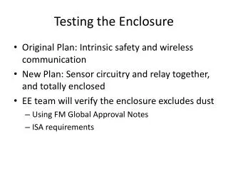
Feasibility- Water Ingress Test • Need: The external package should resist minor splashing • Specification: Water Ingress Tests • Once model is constructed, (user interface, connectors sealed, lid in place) exclude internal electronics and perform test • Monitor flow rate (length of time and volume) of water • Asses the quality to which water is prevented from entering case by examining water soluble paper • Risk: Water can enter the external package and harm the electronics • Preventative measures: • Spray on Rubber Coating or adhesive • O-rings around each screw well and around the lid • Loctite at connectors • Preliminary Tests without protective coating show no traceable water ingress Loctite Spray on Rubberized Coating
Feasibility- Robustness Testing • Need: The device should survive a fall from the hip • Specification: Drop Test • Drop external housing 3 times from 1.5 m, device should remain fully intact • Specify and build internal electrical components • Identify the “most vulnerable” electrical component(s) which may be susceptible to breaking upon a drop • Mimic those components using comparable (but inexpensive and replaceable) electrical components, solder on point to point soldering board • Goal • Show the housing will not fail • Show electronics package will not fail, when subjected to multiple drop tests • Risks • The housing fails before the electronic components in drop tests (proved unlikely with prototype enclosure) • The electronic components can not survive multiple drop tests • Preventative Measures • Eliminate snap hinges from housing (tested and failed) • Test the housing first • Design a compact electronics package
Feasibility- Heat Dissipation of Internal Components • 130°C is absolute maximum for chip junction temperature in order to function properly • Goal- comfort for the user • Assumed steady state, heat only dissipated through 3 external surfaces • Maximum heat dissipation ~25W • Actual heat dissipation ~5W Tout Tin h Q t, k
Prototype Enclosure • Survived drop test • Water resistant • Plastic is machinable • Drilled, tapped, milled • Helicoilsshould be used to tap holes • Constant opening and screwing and unscrewing of lid will result in stripped threads • Approximate wall thickness (6mm) • Distance between center of holes and wall needs to be increased • Some cracking occued • Latches are not feasible
User Interface From Pump To Battery BATTERY MENU + Speed Battery Life Fault Indication To Battery To/From Computer ERROR OK - Components: Indication of battery life (3x LED) Indication of Fault (LED and Buzzer) Indication of levitation (LED) Display Increase/Decrease Speed (2x Button) Menu (Button) Connectors: 26- pin LEMO connector USB connector Battery Terminals (x2) OK: Indication of levitation ERROR: No Levitation, connection errors
User Interface- Components LED Backlit display with waterproof bezel and o-ring G/R/Y LEDs with O-ring and waterproof bezel Waterproof buttons with O-ring
User Interface- Connectors Current Model: Part # EGG 2K 326 CLL Proposed: Part # EEG 2K 326 CLV Pin Layout