Download

1 / 76
770 likes | 1.01k Vues
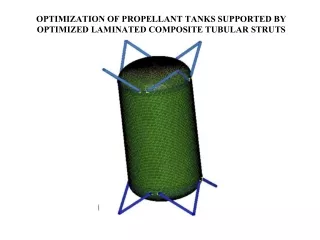
OPTIMIZATION OF PROPELLANT TANKS SUPPORTED BY OPTIMIZED LAMINATED COMPOSITE TUBULAR STRUTS. OPTIMIZATION OF PROPELLANT TANKS SUPPORTED BY OPTIMIZED LAMINATED COMPOSITE TUBULAR STRUTS. David Bushnell, AIAA Fellow, 775 Northampton Drive, Palo Alto, California 94303

E N D
OPTIMIZATION OF PROPELLANT TANKS SUPPORTED BY OPTIMIZED LAMINATED COMPOSITE TUBULAR STRUTS
OPTIMIZATION OF PROPELLANT TANKS SUPPORTED BY OPTIMIZED LAMINATED COMPOSITE TUBULAR STRUTS David Bushnell, AIAA Fellow, 775 Northampton Drive, Palo Alto, California 94303 Michael S. Jacoby, Lockheed Martin Missiles and Space, Palo Alto, California 94304 Charles C. Rankin, AIAA Associate Fellow, Rhombus Consultants Group, Inc., 1121 San Antonio Rd., Palo Alto, CA 94303
Summary • What is GENOPT? (Slides 4 - 17) • What is BIGBOSOR4? (Slides 18 and 19) • Problem formulation (Slides 20 and 21 and 22) • Geometry (Slides 23 - 33) • Objective versus design iterations for SUPEROPT execution (Slide 34) • Vibration modes & frequencies from GENOPT/BIGBOSOR4 (Slides 35, 36) • Design Sensitivity of the optimized tank/strut system (Slide 37) • Strut buckling as a thin, axially compressed cylindrical shell (Slide 38) • Prebuckling deformation and stress in the propellant tank (Slide 39) • Buckling of the propellant tank (Slide 40) • What is STAGS (Slide 41) • Predictions from the STAGS computer program (Slides 42 - 64) • Optimized tank mass and conductance vs number of strut pairs (Slides 65 - 66) • Comparison STAGS and GENOPT/BIGBOSOR4 results (Slides 67 - 72) • Conclusions (Slides 73 - 76)
What is BIGBOSOR4? • Stress, buckling and vibration of elastic shells of revolution (BIGBOSOR4=BOSOR4 with more shell segments permitted, up to 295 shell segments as of 2011). • Springs can be attached to rigid ground • Nonlinear axisymmetric stress analysis • Linear non-axisymmetric stress analysis • Axisymmetric or non-axisymmetric bifurcation buckling • Linear vibration modes of axisymmetrically loaded shell • Multi-segment, branched, ring-stiffened shells of revolution • Various wall constructions • BIGBOSOR4 cannot handle local shell segment transverse shear deformation (t.s.d.) or local shell wall anisotropy or bifurcation buckling with applied in-plane shear loading. Use a factor of safety to compensate for these effects on local buckling.
Matrices governing vibration and buckling of shells of revolution derived via BIGBOSOR4 are narrowly banded
Propellant tank/strut system is optimized subject to: • the minimum modal vibration frequency must be greater than a given value • five stress components in each ply of the laminated composite wall of the strut tubes shall not exceed five specified allowables • no strut tube shall buckle as a column • no strut tube shall buckle as a thin cylindrical shell • the maximum effective (vonMises) stress in the tank wall shall not exceed a specified value • the tank wall shall not buckle • the maximum force in a strut during the launch-hold phase of a mission shall not exceed a specified value
The objective is: • Objective= W x (normalized empty tank mass) + (1-W) x (normalized strut conductance), in which W is a user-selected weight between 0.0 and 1.0
Optimization in the presence of two load cases: • Load Case 1: 10g axial acceleration plus 25 psi internal ullage pressure plus 200-degree cool-down of the propellant tank • Load Case 2: 10g lateral acceleration plus 25 psi internal ullage pressure plus 200-degree cool-down of the propellant tank
Long Propellant tank with two sets of struts, aft and forward
Plan view of the aft set of struts, starting design, 4 pairs of struts
Sketch of propellant tank strut support ring and tapered doubler
Elevation view of optimized design. Only one pair of the 4 pairs of struts is shown at each axial location.
Elevation view of the optimized short propellant tank with only one “ring” of struts
Plan view of optimized long propellant tank/struts with only 2 pairs of struts at each axial location
Plan view of optimized long propellant tank/struts with 3 pairs of struts at each axial location
Plan view of optimized long propellant tank/struts with 5 pairs of struts at each axial location
Objective=WGT x TOTMAS/TNKNRM +(1-WGT) x CONDCT/CONNRM during the 1st execution of SUPEROPT
4 vibration modes from BIGBOSOR4 for the optimized long propellant tank with aft and forward struts
3 vibration modes from BIGBOSOR4 for the optimized long propellant tank with aft and forward struts
Design sensitivity of the optimized tank/strut system with respect to AGRND(1)
Aft strut buckling as a thin cylindrical shell rather than as a column
Deformed meridians of the long propellant tank under (A) Load Case 1 and (B) Load Case 2
What is STAGS? • STAGS [16 -19] is a finite element code for the general-purpose nonlinear analysis of stiffened shell structures of arbitrary shape and complexity. Its capabilities include stress, stability, vibration, and transient analyses with both material and geometric nonlinearities permitted in all analysis types. A large rotation algorithm that is independent of the finite element library has been incorporated into STAGS. Solution control in nonlinear problems includes specification of load levels or use of the advanced Riks-Crisfield path parameter that enables traversal of limit points into the post-buckling regime. Two load systems with different histories (Load Sets A and B) can be defined and controlled separately during the solution process. Imperfections can be generated by superposition of several buckling modes determined from previous STAGS analyses of a given case. “Shell units” can be modeled with minimal user input as individual substructures in which the analytic geometry is represented exactly. Complex structures can be assembled from multiple relatively simple shell units or from a finite element unit.
STAGS model of the optimized long propellant tank with two sets of struts, aft (Lower) and forward (Upper)
Revised STAGS model of the optimized long propellant tank with two sets of struts