7-Segment Displays
This discussion explores the implementation of 7-segment displays on the Digilent Spartan 3 board using VHDL. It covers the design of a 7-segment decoder, multiplexing techniques to drive multiple displays, and the control logic for turning LEDs on/off based on input values. Key components include the architecture of VHDL modules such as x7seg, ctr2bit, and ANcode, detailing how to manage the segments and enable signals for efficient display management. Learn how to effectively manipulate and visualize binary data on 7-segment displays.

7-Segment Displays
E N D
Presentation Transcript
7-Segment Displays Digilent Spartan 3 Board Discussion D8.2
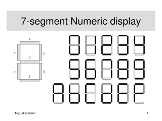
7-Segment Decoder a-g LOW to turn on segment
Multiplex displays 1 1 1 0 0 0 0 0 1 1 0
Multiplex displays 1 1 0 1 0 0 0 1 1 1 1
Multiplex displays 1 0 1 1 1 0 0 1 1 0 0
Multiplex displays 0 1 1 1 0 1 1 1 0 0 0
x7seg.vhd library IEEE; use IEEE.STD_LOGIC_1164.ALL; use IEEE.STD_LOGIC_ARITH.ALL; use IEEE.STD_LOGIC_UNSIGNED.ALL; entity x7seg is Port ( x : in std_logic_vector(15 downto 0); cclk, clr : in std_logic; Aen : in std_logic_vector(3 downto 0); AtoG : out std_logic_vector(6 downto 0); AN : out std_logic_vector(3 downto 0) ); end x7seg;
architecture arch_x7seg of x7seg is signal dig0, dig1, dig2, dig3: std_logic_vector(3 downto 0); signal digit : std_logic_vector(3 downto 0); signal count : std_logic_vector(1 downto 0); constant bus_width: positive := 4; begin
use IEEE.std_logic_1164.all; use IEEE.std_logic_unsigned.all; entity ctr2bit is port ( clr: in STD_LOGIC; clk: in STD_LOGIC; q: out STD_LOGIC_VECTOR (1 downto 0) ); end ctr2bit; architecture ctr2bit_arch of ctr2bit is signal COUNT: STD_LOGIC_VECTOR (1 downto 0); begin process (clk, clr) begin if clr = '1' then COUNT <= "00"; elsif clk'event and clk='1' then COUNT <= COUNT + 1; end if; end process; q <= COUNT; end ctr2bit_arch;
library IEEE; use IEEE.std_logic_1164.all; entity ANcode is port ( Aen: in STD_LOGIC_VECTOR (3 downto 0); Asel: in STD_LOGIC_VECTOR (1 downto 0); AN: out STD_LOGIC_VECTOR (3 downto 0) ); end ANcode;
architecture ANcode_arch of ANcode is begin process(Aen, Asel) begin AN <= "1111"; case Asel is when "00" => if Aen(0) = '1' then AN <= "1110"; end if; when "01" => if Aen(1) = '1' then AN <= "1101"; end if; when "10" => if Aen(2) = '1' then AN <= "1011"; end if; when others => if Aen(3) = '1' then AN <= "0111"; end if; end case; end process; end ANcode_arch;
Port Maps u0: ctr2bit port map (clr => clr, clk => cclk, q => count); u1: mux4g generic map(width => bus_width) port map (a => dig0, b => dig1, c => dig2, d => dig3, sel => count, y => digit); u2: seg7dec port map (q => digit, AtoG => AtoG); u3: ANcode port map (Aen => Aen, Asel => count, AN => AN);
.ucf file NET "AN<0>" LOC = "E13" ; NET "AN<1>" LOC = "F14" ; NET "AN<2>" LOC = "G14" ; NET "AN<3>" LOC = "d14" ; NET "AtoG<6>" LOC = "E14" ; NET "AtoG<5>" LOC = "G13" ; NET "AtoG<4>" LOC = "N15" ; NET "AtoG<3>" LOC = "P15" ; NET "AtoG<2>" LOC = "R16" ; NET "AtoG<1>" LOC = "F13" ; NET "AtoG<0>" LOC = "N16" ; NET "dp" LOC = "P16" ;