Download
1 / 13
130 likes | 209 Vues
This essential guide goes over what a load cell is, the history of load cells and much more information about load cells.

E N D
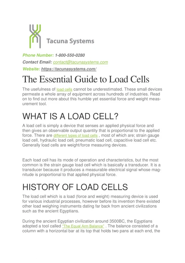
Phone Number: 1-800-550-0280 Contact Email: contact@tacunasystems.com Website: https://tacunasystems.com/ The Essential Guide to Load Cells The usefulness of load cells cannot be underestimated. These small devices permeate a whole array of equipment across hundreds of industries. Read on to find out more about this humble yet essential force and weight meas- urement tool. WHAT IS A LOAD CELL? A load cell is simply a device that senses an applied physical force and then gives an observable output quantity that is proportional to the applied force. There are different types of load cells , most of which are; strain gauge load cell, hydraulic load cell, pneumatic load cell, capacitive load cell etc. Generally load cells are weight/force measuring devices. Each load cell has its mode of operation and characteristics, but the most common is the strain gauge load cell which is basically a transducer. It is a transducer because it produces a measurable electrical signal whose mag- nitude is proportional to that applied physical force. HISTORY OF LOAD CELLS The load cell which is a load (force and weight) measuring device is used for various industrial processes, however before its invention there existed other load weighing instruments dating far back from ancient civilizations such as the ancient Egyptians. During the ancient Egyptian civilization around 3500BC, the Egyptians adopted a tool called “The Equal Arm Balance” . The balance consisted of a column with a horizontal bar at its top that holds two pans at each end, the
bar and the pans are attached to each other by a rope. Below is a picture of the balance. Figure 1: Equal Arm Balance Then 2500 years after this, a form of unequal arm balance called the “steel yard balance” was invented by the Romans. It consisted of a scaled metal arm suspended off center from above by a hook close to the shorter arm and a known weight called a poise that was attached to the longer arm. This allowed it to gradually slide until it balanced the load attached to the shorter arm. The weight of the unknown load is then obtained based on the position of the poise on the calibrated arm. Below is a picture of a steelyard balance. Figure 2: Steel Yard Balance Moving forward, Leonardo Da Vinci invented a gradual dial scale in the late 15th century and this marked a great milestone in weight measuring tech- nologies. It was the first automatic balance system that used the position of the calibrated weights on a mechanical lever to balance and determine an unknown weight. In the 16th century, the Roberval scale was made by the French mathema- tician called Gilles Personne de Roberval.
In the 17th century, spring scales were invented and they created a non- counter weight approach to weight measurement, which is based on Hooke’s law. The scale consists of a spring attached at one end, a hook at the other end to which the object to be weighed is attached and a pointer that moves along the markings on the body of the scale. The position of the pointer is proportional to the weight attached to the hook, that is, the weight attached stretches the internal spring of the device. The devices mentioned above were the major weight measuring devices that existed before actual load cells were invented. Pneumatic and hydrau- lic load cells were the first set of load cell designs to exist before strain gauge load cells. The English physicist Sir Charles Wheatstone devised the bridge circuit in 1843, it measured electrical resistances. This circuit formed the basis for modern load cell circuitry as the arms of the bridge circuit are fixed with strain gauges. The strain gauge is a bonded wire device that changes its resistance when it is deformed (stretched/contracted). Strain gauge load cells are the most common form of load cells due to their ability to support large load sizes. However Pneumatic and Hydraulic load cells still find their applications in some certain industries. The advent of strain gauge load cells then resulted in the invention of what is called digital scales, which offer better and more precise load measure- ment values than earlier weight measurement devices. HOW DO LOAD CELLS WORK? Load cells use compressive, bending and tensile force actions to indicate the size of a load. Each type has its basic mode of operation and they are explained below: Pneumatic load cells Its operation depends on air or gas operated under pressure in a confined space, hence it is a force balance device. The load force to be measured is applied to the top of the diaphragm, the force then creates a pressure that causes the air or gas inside the container to escape through the nozzle and then deflect the pressure gauge.
Figure 3: A Simple Pneumatic Load Cell Figure 4: A model YGXD305 Pneumatic load cell manufactured by YGX Tech. Hydraulic load cells This is quite similar to the pneumatic type, but uses a piston-cylinder ar- rangement that uses a liquid medium under pressure in a confined space, this also makes it a force balance device. The load force to be measured is applied to the piston, this force pushes the piston downwards and deflects the diaphragm, this deflection then in- creases the pressure in the liquid medium. In other words, the increase in pressure is proportional to the size of the applied force, this change in pressure is then transmitted to the bourdon tube pressure gauge by the liquid medium. It should be noted that the pres- sure calibration is in Newton, hence the value indicated on the pressure
gauge is a measure of the force applied on the piston. Figure 5: A Diagram of a Hydraulic Load Cell. Figure 6: A model F1108 Hydraulic load cell manufactured by TECSIS Strain gauge load cells A strain gauge load cell is a force sensor and also a transducer device. It is a transducer that senses an applied load (force weight) and then changes it into an electrical signal output that is proportional to the load. When a load is placed on the load application point of the load cell, it causes a deformation in the dimensions of the underlying strain gauge, this deformation creates changes in its electrical resistance, hence changes in
the output electrical voltage. The voltage is then conditioned to give the proportional value of the load applied. Figure 7: A Binocular beam load cell Figure 8: A model 108BS Stainless Steel Single Point Load Cell manufactured by AnyLoad WHAT ARE THE DIFFERENT LOAD CELL TYPES? There are three major types of load cells, namely: Hydraulic load cells Pneumatic load cells Strain gauge load cells The strain gauge load cell comes in varieties of designs and shapes, but they are majorly of three categories; the full bridge strain gauge load cell (four strain gauge), the half bridge load cell (two strain gauge) and the quarter bridge load cell (one strain gauge). Other types of load cells are:
Vibrating wire load cell Capacitor load cell Piezoelectric load cell WHAT ARE THE MATERIALS USED IN COMMERCIAL LOAD CELLS? The different load cell types are made from different material parts. Alt- hough the different designs of a particular load cell type have common ma- terial parts, this section focuses on the material parts of the three common load cells and they are: Pneumatic load cells: A pneumatic load cell has the following parts; an elastic diaphragm attached with a platform surface to which force can be applied, an air supply regulator, a nozzle and a pressure gauge. Its metal body parts are made of stainless steel. Figure 3 above shows the basic parts of a pneumatic load. Hydraulic load cells: Its main parts are; an elastic diaphragm, a piston with a loading platform placed on top of the diaphragm, a liquid medium and a bourdon tube pressure gauge. The metal body parts are always made from stainless steel. Figure 5 above shows the basic parts of a hy- draulic load cell. Strain gauge load cells: The major material in this load cell is the strain gauge, they are arranged to form the arms of a Wheatstone bridge circuit. Other components are the spring element, the sealing element and the casing of the device. The casing and other metallic parts of the load cell are usually made from stainless steel. Other basic elements that make up a strain gauge load cell include the spring element, the sealing elements and the housing that helps to protect the load cell components. It can be seen that they do have some material parts in common especially the metallic parts which is manufactured majorly from Stainless steel. Stainless steel is used by Original Equipment Manufacturers (OEMs) be- cause of its broad range of properties that enable it to withstand great physical stress, thermal stress and bear high loading conditions. WHAT ARE LOAD CELLS USED FOR?
Generally load cells are used for various load bearing and weight/force measuring applications, hence they are LOAD (FORCE and WEIGHT) MEASURING DEVICES. Their ability to sense force, load and weight makes them applicable in vari- ous diverse industries such as the medical and pharmaceutical industry, manufacturing industry, automotive industry, research laboratories, agricul- tural industry, aerospace and defense industry, robotics systems industry, marine industry, oil and gas industry etc. They are found in various devices such as weight checkers, weighing scales, medical devices, platform and industrial scales, filling and sorting machineries, rolling mill systems etc. Load cells are used in devices for various processes such as process weighing, parts counting, medical equipment testing, pile testing, process control and automation monitoring. They’re also used in wire tension meas- urement, silo weight measurement and monitoring, automated container fill- ing, robot tactile sensing and batch weighing. But that’s not all, also in automotive seat testing, aerospace structural test- ing, spring testing, impact force testing, bin weighing, measuring of tie-rod loads, measurement of load of rolling mills in steel works and detection of remaining amount in gas cylinders, etc. In summary, a load cell is used to measure load (force and weight), its re- sultant output which is the output of the load cell can then be used for other things such as process control and automation. WHAT IS A STRAIN GAUGE LOAD CELL? A strain gauge load cell is one type of load cell, out of the various load cells that exists. It is a force sensor and also a transducer. It is a transducer that senses an applied load (force weight) and then changes it into an electrical signal output that is proportional to the load. The output electrical signal is very small (in mV/V), hence it has to be conditioned to give an output read- ing.
The conditioning may include amplification, attenuation, excitation, filtering and isolation. For amplification, normal operational amplifiers are not effi- cient for the process, hence an instrumentation amplifier is always conven- tionally used in commercial weighing systems. The strain gauge load cell is made out of strain gauges that are electrically connected in a Wheatstone bridge. The Wheatstone bridge can be of different configurations which are; one strain gauge (Quarter Bridge), two strain gauges (half bridge) and four strain gauges (full bridge). Generally, the number of active elements legs in the Wheatstone bridge determines the kind of bridge configuration. Figure 9: A full bridge strain circuit The strain gauge is a bonded resistive foil sensor which is capable of stretching and contracting, its resistance varies with applied load. The ma- terial deforms/stretches and contract, they are bonded onto a beam or a structural member using adhesives. The strain gauges are mounted in ar- eas that exhibit strain in compression or tension. Most strain gauges are
made from a copper-nickel (constantan) alloys, the alloy metal is cut into zigzag foils to form the strain gauge. Figure 10: A Strain Gauge. WHAT IS A TENSION LOAD CELL? Tension load cells are one of the type of strain gauge load cells and are de- signed to measure tensile loads. A tensile load constitute a tensile pulling force, the tensile force is a load that is applied to a material that acts away from the surface it is applied to. In other words it acts to pull the material or object apart or stretch the material it is acting on (in this case, the material being stretched is the strain gauge). Tension load cells are of great use for wound or unwound processes e.g. in the production film and ribbons. If the tensile force is too much, the film can break, rendering it useless and creating a lot of down time as the machine will need to be re-threaded. Also if the tensile force is too low when the film is winding, then the rolls are too loose, leaving them prone to exposure or causing other machines to jam. Tension load cells are also used for more than just film, spring coils are also wound with tension load cells to keep the coils from snapping as the metal is bent. The types of tension load cells include S-beam load cells, columns, and low profile, shackle and link type load cells.
Figure 11: An STA Series S-Type/S- Beam Aluminum Load Cell SAE Thread diagram manufactured by AmCells. HOW OFTEN SHOULD LOAD CELLS BE CALIBRATED? The calibration of load cells is defined as a set of operations carried out to compare the accuracy of the load cell with the standards. Many interna- tional standards such as the ISO9000 specify the maximum period be- tween re-calibration as once every two years and more frequently if the in- strument deterioration is significant during that period. However many users perform annual calibration to ensure that measure- ments are accurate. Some also just compare the current calibration to the previous calibration so as to determine a more suitable re-calibration pe- riod. It should be noted that frequent calibration improves the accuracy and ef- fectiveness of the load cell. Also proper inspection, maintenance and clean- ing of the load cell can help overcome some operational issues that might lead to quick re-calibration. WHO ARE SOME OF THE MORE FAMOUS LOAD CELL MANUFAC- TURERS? This section provides a comprehensive list of the popular industrial load cell manufacturers and suppliers. If you are looking forward to obtaining stand- ard industrial load cells for your weighing system design, here are the pop- ular load cell original equipment manufacturers (OEMS): Amcells
AnyLoad Dale LW Measurements Omega Tacuna Systems WHAT IS THE AVERAGE COST OF A LOAD CELL? The cost of load cells varies with the type of load cell and it depends on several factors such as its rated capacity, its mode of operation, the mate- rial of construction, the requirements of the weighing system etc. The price ranges from about $0.2 for mini load cells to thousands of dollars for load cells with higher rated capacities. Browse our range for a full range of: Load Cells Load Cell Accessories Readouts and Load Cells Indicators THE FUTURE OF LOAD CELLS In the near future, load cells will find more applications in process automa- tion in various industries. Load cells will also find more applications in microsystems, hence resulting into something called Miniaturized Load Cells (MEMS). These load cells will be produced as Micro Electro Mechanical Systems (MEMS), which are the lat- est emerging technologies. MEMS are micro-sized silicon structures etched in the form of beams, dia- phragms or plates that can function as sensors within a load cell. MEMS are fabricated using the bulk and surface micromachining. MEMS can then be mass produced, because thousands of sensor elements can be fabri- cated on single wafer with integrated supporting circuits. Although millions of sensors can be mass produced at a very low price (as low as a few dol- lars), their applications are still limited compared with foil strain gauges. The advantages of these load cells will be higher precision, they will be portable and light weight, enough to be embedded inside materials and even the human body. They can help improve modern medicine and be useful in automatically controlling surgical robot, miniaturized load cell can
be incorporated into strength-training equipment to prevent lifting strain. Also the use of multiple miniaturized load cells in robotic artificial limbs to create toes and fingers that can feel pressure and send that data to the brain so the wearer can respond. Other Sources K. S. K. Singh, “Digital Fuel Indicator in Two Wheelers,” IJSRD – In- ternational Journal for Scientific Research & Development, vol. 2, no. 12, p. 4, 2015. Guide to the measurement of force, published 1998, by the institute of measurement and control, ISBN 0 904457 28 1 Load cell troubleshooting, Technical note VPGT-08, 2015. Digital Load Cells: A Comparative Review of Performance and Appli- cation, published 2003 by the Institute Of Measurement and Control, WP0803. A guide to the specification and procurement of industrial process weighing systems, published 2000 by the Institute of Measurement and Control publication, ISDN 0 904457 32 X British Standard BS EN 30012-1: 1994 Metrological confirmation sys- tems for measuring equipment. W. Boyes, Instrumentation Reference Book, Butterworth-Heinemann, 2009. Phone Number: 1-800-550-0280 Contact Email: contact@tacunasystems.com Website: https://tacunasystems.com/