Download
1 / 18
180 likes | 364 Vues
MapleSim and the Advantages of Physical Modeling. July 22 nd 2010. Why is physical modeling so difficult?. Multidomain / multiphysics Legacy of causal (signal-flow) modeling tools Differential-algebraic equations (DAEs) Fundamental principles in physics and mathematics. An analog

E N D
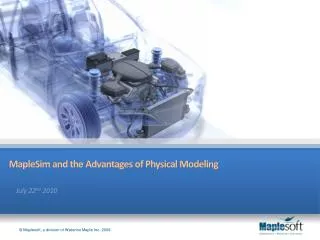
MapleSim and the Advantages of Physical Modeling July 22nd 2010
Why is physical modeling so difficult? • Multidomain/multiphysics • Legacy of causal (signal-flow) modeling tools • Differential-algebraic equations (DAEs) • Fundamental principles in physics and mathematics
An analog computer“program” Simulink is essentiallyan analog computer runningon a PC … A “virtual” analog computer The Story of the Analog Computer
Causal modeling: Challenges... • Complexity of equations does not scale linearly with the size of the system • As complexity/size increases, so does the chance of errors • Prevents high fidelity modeling of larger systems, particularly when applied to plant models Example: 3D pendulum with increasing number of links: * Cost of dynamic equations, joint coordinate formulation, basic symbolic simplify()
Causal modeling: Challenges... • Generated model looks nothing like the formulated equations or model diagram • Assumptions made during equation formulation lost • Hard to track errors • Hard to visually understand the purpose of the system ? R L ~ V ?
Causal modeling: Challenges... • Since these models have predefined inputs/outputs, it is difficult to (properly) connect two causal models • This becomes more important as the scope of models increases (i.e. connect powertrain model to chassis/tire model) • In some cases this can require an equation re-formulation (to be done properly) Engine/Powertrain Inputs Angle ? Chassis/Tire Torque Outputs
F(t) F(t) x1(t) x2(t) M1 M2 d1 d2 k1 k2 Physical Modeling – Faster and Intuitive • Model maps directly to physical components of system • Automatically generates equations of motion Double mass spring-damper system
Maplesoft engineering solution Simulink RTWToolchain MapleSim 4 ControlDesign Toolbox ConnectivityToolboxes LabVIEW RTToolchain CADToolchain Maple 14 Maple Toolboxes
Symbolic computation for plant modeling Standard Numeric Formulation MapleSim Symbolic Formulation Model Definition Model Definition Coordinate Selection Equation Generation Symbolic Simplification Numerical black box Code Optimization Simulation Procedure Generation with Limited Optimization Simulation Procedure Generation with Limited Optimization Simulation Procedure Generation Simulation Simulation
Standard Numeric Formulation • Generated procedure is a set of routines that multiply/add numerical matrices to reformulate the equations at each time step -6 multiplications, 4 additions per step • Certain optimizations can be built into these routines but these are limited, and must be defined ahead of time Model Definition Numerical black box Simulation Procedure Generation with Limited Optimization Simulation
Symbolic computation for plant modeling Standard Numeric Formulation MapleSim Symbolic Formulation Model Definition Model Definition Coordinate Selection MapleSim applies 4 levels of model optimization Coordinate Selection Equation Generation Equation Generation Symbolic Simplification Symbolic Simplification Numerical black box Code Optimization Simulation Procedure Generation with Limited Optimization Simulation Procedure Generation with Limited Optimization Code Optimization Simulation Procedure Generation Simulation Simulation
MapleSim Symbolic Formulation • A model’s chosen state variables directly impact the number and complexity of the resulting equations Model Definition Coordinate Selection Example: Stewart Platform Equation Generation Symbolic Simplification Code Optimization • Absolute coordinates (e.g. ADAMS): • 78 coords (12 per leg, 6 for the platform), • 78 dynamic equations, • +72 constraint equations = 150 equations • Hybrid coordinates (MapleSim): • 24 coords( 3 per leg, 6 for the platform) • 24 dynamic equations • + 18 constraints = 42 equations Simulation Procedure Generation Simulation
MapleSim Symbolic Formulation • Generated equations are true for all time, using the previous example:-2 multiplications, 1 addition per step (versus original 6 and 4, respectively) • Equations can be viewed, analyzed and manipulated in the Maple environment Model Definition Coordinate Selection Equation Generation Symbolic Simplification Code Optimization Simulation Procedure Generation Simulation
MapleSim Symbolic Formulation • Multiplications by 1’s, 0’s automatically removed (previous slide) • Simple equations directly solved, reducing the number of variables to integrate • Trigonometric simplifications: Model Definition Coordinate Selection Equation Generation Symbolic Simplification Code Optimization Simulation Procedure Generation Simulation
MapleSim Symbolic Formulation • Expressions that are repeated within the equations are identified and isolated so they are only computed once Model Definition Coordinate Selection Equation Generation Symbolic Simplification Code Optimization Simulation Procedure Generation Simulation
MapleSim Symbolic Formulation • Using MapleSim’s Addons, optimized procedures can be exported to a variety of targets: • LabVIEW RT Toolchain • Simulink RTW Toolchain • Alternatively, these procedures can be generated in Standalone C-code (no Connectivity Toolboxes required) Model Definition Coordinate Selection Equation Generation Symbolic Simplification Code Optimization Simulation Procedure Generation Simulation
Faster real time simulation • Symbolic multibody model formulation • Model simplification and optimized code generation • More systems become feasible forRT sim