Optical and Copper Cabling Solutions for Pixel Tracker Systems - March 2005 Meeting Summary
150 likes | 272 Vues
This document provides a comprehensive summary of the discussions and action items from the March 9, 2005, meeting regarding optical and copper cabling issues related to pixel tracker systems. It covers the detailed specifications for optical and multi-ribbon cables, including the positioning of MU-SR adapters, techniques for minimizing cable splices, and the design requirements for patch panels. Action items focus on determining cable lengths, sorting for beam monitoring, and reducing the number of control cables. Key decisions and methods for qualification of components are outlined to ensure effective implementation.

Optical and Copper Cabling Solutions for Pixel Tracker Systems - March 2005 Meeting Summary
E N D
Presentation Transcript
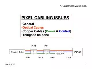
K. Gabathuler March 2005 • PIXEL CABLING ISSUES • General • Optical Cables • Copper Cables (Power& Control) • Things to be done PP1 PP0 USC55 Service Tube Gallery ~ 4-5 m 0.6m ~ 40 m ~ 40 m
Optical Cabling and Patch PanelsMeeting with F. Vasey March 9, 2005 PP1 PP0 Strip Tracker 12 96 1 Do not splice, butuse MU connectoras in Strip Tracker PP0 PP1 Pixel 12 12 96 1 2 m 0.6 m ~50 m? ~4-5 m Special pixel cables
From laser/PIN-diode to MU connector 2.0 m, cannot be changed MU connector Laser/PIN introduce loops (r > 3 cm) AOH AOH 59 mm MU-SR 12 way adapter Position and length of loops, andposition of MU-SR 12 way adaptermust be carefully chosen in z! 4 cm barrel: z=50-70 cm barrel: z=200-250 cm All in service tube
From MU-SR 12 way adapter to PP0 0.3 m, fixed ~ 0.3 – 0.7 m, to be determined 12-ribbonconnector PP0 MU-SR 12 way adapter
From PP0 to PP1 special cables for pixel,F. Vasey will get tender for us. A total of 260 ribbons. Lengths determined from mock-up. On the way from PP0 to PP1, thereis sorting into readout/control/spare//beam-monitoring groups. 12-ribbonconnector 12-ribbonconnector ~ 4-5 m
PP1 Ribbons from PP0 Multi-ribbon cables to FED/Cs
From PP1 To USC55
From PP1 to USX55: 34 multi-ribbon cables PP1 FED/FEC
Copper Cables • Control cables for: • T-sensors • H-sensors37 pin connectore.g. 9 T or 8 T + 1 Hfor one cable • Can we reducenumber of cables ? empty empty • Separate power cables(2.5V only) for: • Portcards incl. CCU • All PCB’s on barrel service tube • Needed for power-upsequence
Things to be done soon: • Study position of MU-SR 12 way adapters and the fiber loopsin service tube • Determine lengths of cables going from MU-SR 12 way adapters to PP0 • Determine lengths of pigtails of multi-ribbon cables on FED/FEC side • Decide on number of control cables • Alick: Determine number of cables required for beam-monitoring (lumi-monitor?) • Forward people: Please check all this for your system; irreversible decisions must be taken by May 2005.
Diamond MFS Adaptor Qualification • Brass pre-alignment piece • Steel screw (not removable) • Mount adapted to PP1 cassette. PP1 12 96 1
3D study underway March 2004: Report + proposal for prototype fabrication Production of terminated multi-ribbon cable dependent on successful outcome of complete study FED patch-panel