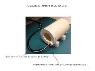
Making Cables for the 8-ch C13 Rat Array
Making Cables for the 8-ch C13 Rat Array. 8 coax cables for RF out from the preamps (black cables). Single twisted-pair cable for 10V & gnd to power premps (white cable). Overview Making JST Power Cables Making Radiall SMP Coax Connections

Making Cables for the 8-ch C13 Rat Array
E N D
Presentation Transcript
Making Cables for the 8-ch C13 Rat Array 8 coax cables for RF out from the preamps (black cables) Single twisted-pair cable for 10V & gnd to power premps (white cable)
Overview • Making JST Power Cables • Making Radiall SMP Coax Connections • Making Smiths/Hypertronics N series Mod K Coax Connections • Making Smiths/Hypertronics N series Mod V Signal Connections • Making Cable Traps
Whether your scanner is a GE, Siemens, Philips, Bruker, etc., the far end of the cable that plugs into the scanner will have proprietary connections. As a researcher at an institution that has access to proprietary information (one that has signed a research agreement, a legal document), you have to be aware to not divulge any of those companies’ intellectual property. Those companies typically buy their connectors from 3rd party connector companies and/or have special parts made for them (of special non-magnetic, non-contaminated plating alloys, etc.). There are many such connector companies (ODU, Smiths/Hypertronics, Huber & Suhner and so on.) These slides won’t go over any proprietary connections, but rather simply go over the mechanics of making crimp connections of a few types of relevant connectors, so that you can fix your cables if/when they break. When most complicated pieces of equipment do break, it’s usually the connectors that have gone bad.
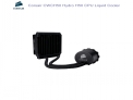
A Typical MRI Scanner Connector An ID chip (EEPROM), similar to the ID chips for printer toner cartridges Single-wire connectors for low-frequency control signals and power/gnd Coaxial connectors for RF out from each coil in the array Mechanical (only) guide posts for alignment Plastic case is mostly cosmetic, but can be useful to provide strain relief during handling
Of course, on your end of the cable, you can design with whatever connectors you like. Here we use JST 2-pin connectors for power/gnd, and Radiall’s SMP miniature coax connectors for RF signals. No connectors are used between the coil and the preamp board. We simply solder/unsolder the coil neck ends to two pads on each preamp board. JST 2-pin power conns Radiall SMP coax conns
Overview • Making JST Power Cables • Making Radiall SMP Coax Connections • Making Smiths/Hypertronics N series Mod K Coax Connections • Making Smiths/Hypertronics N series Mod V Signal Connections • Making Cable Traps
JST SFHR-02V-R JST SSFH-001T-P0.5 JST WC-SFH1 JST SM02B-SFHRS-TF(LF)(SN) Using 26 AWG stranded wire (Alpha Wire #3049), available from Mouser. Contact JST to ask for crimping instructions and strip length. JST, like most connector vendors, does not post crimping instructions on their web site.
Important! Make sure that whether you choose #22, #24 and #26 wire, that you choose one with an outer diameter less than 1.3 mm!
Make sure to check the datasheet for the wire you use or measure the outer diameter. This Alpha Wire (#3049) 26 AWG wire’s outer diameter is just barely less than 1.3 mm. Similar 24 AWG wire that I tried was too large and the crimp didn’t work (the cable fell apart). Check the manufacturer’s web site for datasheets, before you buy wire.
Use diagonal cutters that have a flush backside and pointy tips: Xcelite (Digikey #MS543JV)... ...to snip the stripped length to 1.7 mm:
A proper crimp should come out looking like this: The stripped length should be precisely 1.7 mm so that the wire strands end here, below where the mating pin will reach: This upper tang should grab solely stripped metal. This lower tang should grab the insulation.
These bend-overs won’t be changed by the crimp tool. This bend-over is what accepts the mating pin that’s in the receptacle that this plug will plug into. The crimp tool is designed to crimp these lower 2 tangs around your wire.
If you simply hold your ~1.7 mm length of stripped wire up to the contact which is sitting in the back flap, you can see if the strip length is correct. The outer tang should be able to grab onto the insulation, so the outer tang should come to about this position on your wire:
Now, with the contact in the back flap’s hole marked 26 AWG, fold up the back flap ... ... from the front, the contact looks like this:
Carefully, insert the wire all the way in, making sure the outer tang will be able to grab the insulation. Then squeeze until the handles spring back. Notice, that as you gradually release, you can’t actually get your crimped wire out now ...
To get your crimped wire out, you now have to tilt the back flap back a few degrees ... ... now you can pull it out.
Top surface These pins are positioned towards the top of this board-mount connector, so this contact has to have this part that slides over that pin, oriented towards the top also, when we slide it into the plug. Plug top surface
On the preamp board and on the power distribution ribbon, I defined the leftside pin as ground. Here we’ll use black as the color of the wire to be connected to ground.
Plug bottom surface This tang orients towards the bottom and latches. Plug top surface (top is flatter than the bottom)
This front lead and the one on the far side are just for mechanical attachment to the board. They aren’t connected to the internal pins. The board footprint is laid out for this lead to be +10 V. Ground
On the power distribution ribbon, the yellow connector is where the cable will bring 10 V and ground to this power ribbon. Then the power distribution ribbon has a separate red power connector for each preamp board. For each preamp board, we need to make a power cable to connect here and here:
Think first, before inserting the contacts into the other plug. The way the boards are laid out, we need this way:
Always ohm-out power and ground connections after you make power cables. Make sure ground and one board is connected to ground on another board. Check 10 V locations on each board. Make sure a 10 V location is not connected to ground, etc. Don’t skip this step. It’s not worth it (the preamps are $145 each and have a 6-week lead time).
Overview • Making JST Power Cables • Making Radiall SMP Coax Connections • Making Smiths/Hypertronics N series Mod K Coax Connections • Making Smiths/Hypertronics N series Mod V Signal Connections • Making Cable Traps
SMP coaxial connectors: Once the plug and receptacle are mated, we need a special SMP separation tool to get them apart. SMP separation tool To scanner SMP right-angle plug To probe coil SMP surface-mount receptacle (sends RF_out from the preamp to the scanner cable) First though, we need to attach the SMP right-angle plug to a piece of coax cable ...
How do we attach the SMP right-angle plug (this SMP plug is made for RG-316 coax) to the cable? When you buy this connector (Radiall #R222.900.357W), it comes with a ferrule and a cap: ferrule cap
Radiall R222.900.357W SMP (non magnetic) right angle plug http://www.radiall.com/media/files/NonMagnetic%20D1C004XEe.pdf First, strip the (non-magnetic) RG-316 coax to these dimensions: 1.3 mm 1.5 mm 5 mm
Parameters for coax stripping RG316 for SMP plugs: Step 1: Strip length 2.8 mm Wire dia 1.25 mm Wire drawback 4 mm Blade wayback 0.1 mm Cut time 1 sec Rotary twist 0 (no) Step 2: Strip length 1.3 mm Wire dia 0.5 mm Wire drawback 4 mm Blade wayback 0.1 mm Cut time 1 sec Rotary twist 1 (yes) Step 3: Strip length 7.8 mm Wire dia 2.15 mm Wire drawback 10 mm Blade wayback 0.1 mm Cut time 1 sec Rotary strip 0 (no) Kingsing KS-09S coax stripper www.kingsing.sh Hint: use a vise grips (Quick-Grip with rubber jaws) to hold onto
Note: slide the ferrule onto the wire before flaring the braid! Don’t forget this step! I use a sharp scalpel’s point to gently flare the braid. Since this particular coax cable from Elspec has an inner foil, sometimes you need to slice it in order to flare it out.
Inner conductor slides over top this gold post inside the plastic insulator: Outer conductor goes outside the knurled shaft of the SMP plug Plastic insulation surrounding gold post Inner conductor The crazy part is that we actually need to solder the inner conductor to that gold piece ... But that’s a later step. First, we need to crimp the outer conductor ...
Radiall R222.900.357W SMP (non magnetic) right angle plug Daniels crimp frame HX4 Daniels die set Y196, cavity A ...for the outer crimp of the Emerson SMA bulkhead-cable jack, #142-9303-411 Y196 cavity A
Slide the ferrule down over the outer braid. The ferrule is what we’re crimping to the knurled shaft:
Now that we’ve connected the outer braid of the cable to the outer shell of the SMP plug, we next have to connect the cable’s inner conductor to the SMP plug’s signal pin. This means we have to solder this inner conductor to this gold post: The only chance of soldering this sucessfully is if you have a beveled tip like this. The “bevel” means is has a flat edge here: We’ll put that flat edge so it contacts both the inner conductor and the gold post, so as to heat them simultaneously.
Also, there is absolutely no chance to be successful unless you apply flux. Flux is the magical chemical that makes soldering work. The soldering process is a highly engineered system – flux is corrosive and gets rid of the oxide, allowing the two metal surfaces to get soldered together:
After applying flux, heat both the inner conductor and the gold post at the same time:
Then bring in a bit of solder (if you’re using lead-free solder, you need to use flux made for lead-free solder). There is no chance to get this to work unless you sit down and fixture your arms and hands against the desk, and the vise, using your palms and wrists to wrap around the vise:
It should end up like this – a solder fillet on top of the gold post, with no solder shorting to the sides of the aluminum cavity:
Verify that there is no solder shorting the inner conductor to the outer shell, by ohming them out. You can also ohm out the opposite end of the cable to check.