Download
1 / 37
380 likes | 628 Vues
Deepwater Floating Offshore Wind Turbine Control Methods. Hazim Namik Department of Mechanical Engineering. Outline. Introduction to wind turbines Offshore wind turbines Wind resource Floating wind turbines Control Methods Summary. Introduction.

E N D
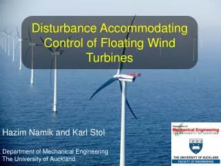
Deepwater Floating Offshore Wind Turbine Control Methods Hazim Namik Department of Mechanical Engineering
Outline • Introduction to wind turbines • Offshore wind turbines • Wind resource • Floating wind turbines • Control Methods • Summary
Introduction • Wind energy is the fastest growing renewable energy • Wind energy is a form of solar energy • Only 2% of received solar energy is converted to wind • Wind turbines convert some of the wind energy to useful mechanical energy
Types of Wind Turbines • Two main types of wind turbines (WTs) • Vertical axis (VAWT) • Horizontal axis (HAWT) • HAWT are generally more efficient, hence used for power generation
Major Components • Blades • Hub • Nacelle • High speed and low speed shafts • Gearbox • Generator • Yaw drive system Source: US Dept. of Energy
Offshore vs. Onshore Winds • Advantages: • Stronger and steadier winds • Have less turbulence • Have less vertical shear • Winds are more spatially consistent • Disadvantages • The winds Interact with waves • Offshore winds are harder to measure
Vertical Shear • Surface roughness at sea is lower; therefore, higher wind speeds at lower heights. Source: Wind Turbines, Erich Hau
Offshore Resource Availability Source: Goldman, P., Offshore Wind Energy, in Workshop on Deep Water Offshore Wind Energy Systems. 2003, Department of Energy.
Going Further Offshore Source: OCS Alternative Energy and Alternate Use Programmatic EIShttp://ocsenergy.anl.gov/guide/wind/index.cfm
Deepwater Floating Wind Turbines Source: Jonkman, J. Development and Verification of a Fully Coupled Simulator for Offshore Wind Turbines
Source: http://www.mlg.org.au/visual.htm RePower 5MW, 126m diameter rotor Source: RE UK NREL 5MW Wind Turbine • Barge floating platform • 5MW power rating • 126m diameter rotor (3 Blades) • 90m hub height • 153m tall Source: Jonkman, J.M., Dynamics Modeling and Loads Analysis of an Offshore Floating Wind Turbine, in Department of Aerospace Engineering Sciences. 2007, University of Colorado: Boulder, Colorado, USA (to be published).
Control Options Blade Pitch Generator Torque Collective Pitch Pitch to Feather Individual Pitch Pitch to Stall General Turbine Control Methods Mode of Operation Principle of Operation
Floating Turbine Control Methodology Simple Onshore Baseline controller Complex Onshore Special Offshore
Baseline Controller Overview • Generator torque controller • Maximum power below rated wind speed • Regulate power above rated • Collective pitch controller • Regulate generator speed above rated wind speed
Platform Pitching – Problem • Factors affecting platform pitching • Ocean waves • Aerodynamic thrust • Mooring lines
Modifications to the Baseline Controller • Tower feedback loop • Additional blade pitch controller • Tower top acceleration feedback • Active pitch to stall • Extra thrust force when blade is stalled may reduce platform pitching • Detuned controller gains • Reduced pitch to feather controller gains Source: Jonkman, J.M., Dynamics Modeling and Loads Analysis of an Offshore Floating Wind Turbine, in Department of Aerospace Engineering Sciences. 2007, University of Colorado: Boulder, Colorado, USA (to be published).
Results – Tower Feedback • Poor power regulation • Marginally reduced platform pitching Source: Jonkman, J.M., Dynamics Modeling and Loads Analysis of an Offshore Floating Wind Turbine, in Department of Aerospace Engineering Sciences. 2007, University of Colorado: Boulder, Colorado, USA (to be published).
Results – Pitch to Stall • Excellent power regulation • Large platform oscillations Source: Jonkman, J.M., Dynamics Modeling and Loads Analysis of an Offshore Floating Wind Turbine, in Department of Aerospace Engineering Sciences. 2007, University of Colorado: Boulder, Colorado, USA (to be published).
Results – Detuned Gains • Reasonable power regulation • Reduced platform pitching – but not enough Source: Jonkman, J.M., Dynamics Modeling and Loads Analysis of an Offshore Floating Wind Turbine, in Department of Aerospace Engineering Sciences. 2007, University of Colorado: Boulder, Colorado, USA (to be published).
Floating Turbine Control Methodology Current State of Research Worldwide Classical Control Simple Onshore Baseline controller Complex Onshore State space with individual blade pitch Modern Control Nonlinear with individual blade pitch Special Offshore Without adding any actuators Adding necessary actuators
Summary • Offshore winds are stronger and steadier than onshore winds • Floating turbines are economically feasible for deep waters • Classical control was not successful at controlling a floating wind turbine • Modern control with state space or nonlinear control is the way to go
Water Depths Source: Henderson, A.R., Support Structures for Floating Offshore Windfarms, in Workshop on Deep Water Offshore Wind Energy Systems. 2003, Department of Energy.
Floating Wind Turbines • Reduce the cost of construction for deep waters • Can be located close to major demand centres • Could interfere with aerial and naval navigation • Harder to control as added dynamics of platform motion affect performance
Power Regions • Region 1 • No power is generated below the cut in speed • Region 2 • Maximise power capture • Region 3 • Regulate to the rated power
Torque Controller • Region 1 • Region 2 • Region 3 • Regions 1.5 and 2.5 are linear transitions between the regions
Region 2.5 Torque Controller Region 1.0 Region 1.5 Region 2.0 Region 3.0
Collective Pitch Controller • PI Controller to regulate generator speed • Controller gains calculated according to the design parameters • ωn = 0.7 rad/s and ζ = 0.7 • Simple DOF model with PI controller gives
Pitch Sensitivity • Power sensitivity to blade pitch is found through linearization of the turbine model • Pitch sensitivity varies almost linearly with blade pitch • Gain Scheduled PI gains are calculated based on blade pitch through a gain correction factor GK(θ)
Baseline Controller in SIMULINK Data Extraction and Plotting Controllers FAST Engine
R2 Torque Gain Derivation Cont. • Changing to generator torque and HSS speed in rpm and taking pre-cone into account • In Region 2, CP = CP,Max and λ = λo • For this Turbine: • CP,Max= 0.482, λo= 7.55, R= 63m, α=2.5°, and NGear= 97
Why N3 • At steady state TGen = THSS
Pitch Controller Derivation • Single DOF model of the turbine drivetrain gives • Taylor approximation of aerodynamic and generator torques gives
Pitch Controller Derivation (Contd.) • Pitch commands (Δθ) comes from the PID controller equation • By making the following substitution and replacing everything in the equation of motion, we get
Pitch Controller Derivation (Contd.) • This is a 2nd order differential equation • Expanding ωn and ζ and solving for a PI controller (KD = 0) gives