Download
1 / 37
390 likes | 804 Vues
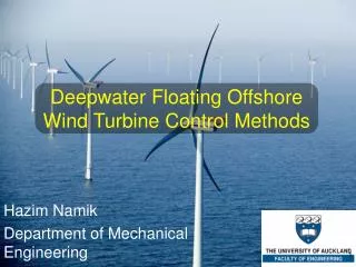
Disturbance Accommodating Control of Floating Wind Turbines. Hazim Namik and Karl Stol Department of Mechanical Engineering The University of Auckland. Outline. Introduction Individual vs. Collective Blade Pitching Implemented controllers Gain Scheduled PI Periodic LQR Periodic DAC

E N D
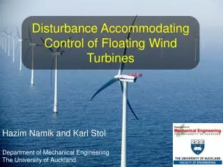
Disturbance Accommodating Control of Floating Wind Turbines Hazim Namik and Karl Stol Department of Mechanical Engineering The University of Auckland
Outline • Introduction • Individual vs. Collective Blade Pitching • Implemented controllers • Gain Scheduled PI • Periodic LQR • Periodic DAC • Results • Summary 2
Introduction • A recent trend in the wind turbine industry is to go offshore • The further offshore the better the wind BUT increased foundation costs • After certain depth, floating wind turbines become feasible 3
Floating Wind Turbines Source: Jonkman, J.M., Dynamics Modeling and Loads Analysis of an Offshore Floating Wind Turbine, in Department of Aerospace Engineering Sciences. 2007, University of Colorado: Boulder, Colorado. 4
NREL 5MW Wind Turbine • Barge floating platform • 40m×40m×10m • 5MW power rating • 126m diameter rotor (3 Blades) • 90m hub height • Simulated using FAST and Simulink 5
Previous Work • Implemented a time-invariant state space controller to address multiple objectives • Power and platform pitch regulation • Performance was improved but... • Conflicting blade pitch commands were issued due to collective blade pitching • Individual blade pitching was proposed
Objectives and Scope • Implement individual blade pitching through periodic control • Compare performance of DAC on a floating barge system to previously applied controllers • Disturbance rejection for wind speed changes only • Above rated wind speed region only • Barge platform only
Control Options Blade Pitch Generator Torque Collective Pitch Individual Pitch How to Control a Wind Turbine? Source: US Dept. of Energy 8
Collective Pitch Restoring Mechanism • Works by changing the symmetric rotor thrust • As turbine pitches • Forward: Rotor thrust is increased • Backward: Rotor thrust is reduced • Pitching conflicts with speed regulation 9
Individual Pitch Restoring Mechanism • Works by creating asymmetric thrust loads • As turbine pitches • Forward: • Blades at the top increase thrust • Blades at the bottom reduce thrust • Backward: vice versa 10
Controllers Implemented Gain Scheduled PI (GSPI) Periodic Linear Quadratic Regulator (PLQR) Periodic Disturbance Accommodating Controller (PDAC) 11
Baseline Controller • Generator torque controller • Regulate power above rated • Collective pitch controller • Regulate generator speed above rated wind speed • Gain scheduled PI controller
Periodic gain matrices States vector Actuators vector State Space Control • Requires a linearized state space model • Control law (requires a state estimator)
Periodic LQR • Periodic gains result in individual blade pitching • Requires 5 degrees of freedom (DOFs) model to ensure stability • Platform Roll and Pitch • Tower 1st side-side bending mode • Generator and Drivetrain twist • Part of DAC: State regulation
Disturbance Accommodating Control • Time variant state space model with disturbances • Disturbance waveform model
Disturbance Accommodating Control (Cont.) • Form the DAC law (requires disturbance estimator) • New state equation becomes • To minimize effect of disturbances
Controllers Comparison SISO: Single-Input Single-Output MIMO: Multi-Input Multi-Output
Full DOFs Simulation Result Power and Speed Fatigue Loads Platform Motions
Reasons for Poor Performance • High Gd gain causing extensive actuator saturation • System nonlinearities and un-modeled DOFs • System may not be stable in the nonlinearmodel
Effect of Adding Platform Yaw Power and Speed Fatigue Loads Platform Motions
Conclusions • The periodic LQR significantly improved performance since it utilises individual blade pitching • Adding DAC gave mixed performance due to actuator saturation • DAC for the wind fluctuations may not be the ideal controller for a floating barge concept 23
Future Work • Variable pitch operating point • Follow optimum operating point • DAC for waves • Effect on Bd Matrix • Simple moment disturbance
Offshore Wind Turbines • Why go offshore? • Better wind conditions • Stronger and steadier • Less turbulent • Can be located close to major demand centres • Operate at maximum efficiency (e.g. no noise regulations) • Increased foundation costs with increasing water depth 26
Going Further Offshore Land-Based Shallow Water Transitional Depth Deepwater Floating Water Depth: 0 – 30 m 30 – 50 m 50 – 200 m Source: Jonkman, J.M., Dynamics Modeling and Loads Analysis of an Offshore Floating Wind Turbine, in Department of Aerospace Engineering Sciences. 2007, University of Colorado: Boulder, Colorado. 27
FAST Simulation Tool • Fatigue, Aerodynamics, Structures and Turbulence Source: Jonkman, J.M., Dynamics Modeling and Loads Analysis of an Offshore Floating Wind Turbine, in Department of Aerospace Engineering Sciences. 2007, University of Colorado: Boulder, Colorado. 28
Power Regions • Region 1 • No power is generated below the cut in speed • Region 2 • Maximise power capture • Region 3 • Regulate to the rated power 30
Torque Controller • Region 1 • Region 2 • Region 3 • Regions 1.5 and 2.5 are linear transitions between the regions 31
Region 2.5 Torque Controller Region 1.0 Region 1.5 Region 2.0 Region 3.0 32
Collective Pitch Controller • PI Controller to regulate generator speed • Controller gains calculated according to the design parameters • ωn = 0.7 rad/s and ζ = 0.7 • Simple DOF model with PI controller gives 33
Riccati Equations • Optimal gain and Algebraic Riccati Equation • Optimal periodic gain and Periodic Riccati Equation 35
FAST Aero-hydro-servo-elastic simulator Nonlinear equations of motion Can be linked to Simulink Find linearized state-space model for controller design MATLAB/Simulink Design controllers using linear control theory Easy graphical implementation Powerful design tools to help design controllers Flexible Simulation Tools 36
Periodic Gains • Changes with rotor azimuth • Same for each blade but ±120° out of phase • Gain for state 3 changes sign when blade is at lower half of rotor 37