thermal only
thermal only . Coupled Model for Thermal-Hydrological-Chemical Processes in a High-Level Radioactive Waste Repository in Salt Philip H. Stauffer Los Alamos National Laboratory Los Alamos, NM Nuclear Waste Technical Review Board Marriot Hotel, Albuquerque, NM March 19, 2014.

thermal only
E N D
Presentation Transcript
thermal only • Coupled Model for Thermal-Hydrological-Chemical Processes in a High-Level Radioactive Waste Repository in Salt • Philip H. Stauffer • Los Alamos National Laboratory • Los Alamos, NM • Nuclear Waste Technical Review BoardMarriot Hotel, Albuquerque, NM • March 19, 2014 LA-UR-13-27584 Sandia National Laboratories is a multi-program laboratory managed and operated by SandiaCorporation, a wholly owned subsidiary of Lockheed Martin Corporation, for the U.S. Departmentof Energy's National Nuclear Security Administration under contract DE-AC04-94AL85000. Unclassified Unlimited Release
Los Alamos Team Members • Dylan Harp – Simulation Expert • Amy Jordan – PhD Student • George Zyvoloski – Code Development • Terry Miller – Mesh Generation • Hakim Boukhalfa – Chemistry • FlorieCaporuscio – Chemistry • Bruce Robinson – Project Coordination
Outline • In-drift concept for Defense High Level Waste • Waste composition by thermal load • Background on salt and heat pipes • Simulator description : FEHM developed at LANL • Code validation example • Simulations with heat only • Addition of water and water vapor transport • Processes added to couple water and chemistry • Results of fully coupled Thermo/Hydro/Chem simulations
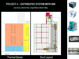
In-drift waste emplacement strategy Simple lower cost method. Backfill is readily available in salt formations Hardin et al., FCRD-UFD-2012-000219 DOE/CBFO-12-3485
Distribution of Heat Loads: DOE-Managed Waste More than 90% of is less than 220W Defense waste heat loads are much lower than commercial SNF heat loads planned for Yucca Mountain (6200 – 8800W/canister) High-Level Waste DOE Spent Nuclear Fuel Carter, J.T., A.J. Luptak, J. Gastelum, C. Stockman, A. Miller. 2012. Fuel Cycle Potential Waste Inventory for Disposition. DOE Office of Nuclear Energy Report FCR&D-USED-2010-000031, Rev 5.
Background • Bedded salt has favorable characteristics for heat-generating waste disposal: • Self-sealing rheology • Very low permeability in its intact/final states • High thermal conductivity • Past heater tests in salt provide datafor basic model validation and salt material properties • Evidence of heat pipe activity around a 130oC heater Heat pipe: Liquid flux (brine) Vapor flux Condensation Hot From Brady et al. (2013). Boiling region
Simulator Description • FEHM developed at Los Alamos 30+ years fehm.lanl.gov • Used for 150+ peer reviewed articles fehm.lanl.gov/pdfs/FEHM_references_list.pdf • Fully coupled thermal, mechanical, chemical, multiphase (gas, water vapor, water, rock) • Uses LaGriT: Powerful 3-D grid generation tool
Code Validation Example SDDI Modeling thermal only • Pile of crushed salt: Radially symmetric simulation Thermocouple 6.4 cm below bulb = porosity • Purpose: • Test crushed salt (RoM) thermalmodel: Stauffer et al., 2013
Thermal only simulation examples Map view of a potential salt repository : in-drift style Reflection boundaries are used to reduce model domain
Thermal only simulation examples Vertical temperature for different 1000W canister spacing Distance from floor (m) 2014 Harpet al., Modeling of High-Level Nuclear Waste Disposal in a Salt Repository, accepted, Nuclear Technology. Temperature (C)
Thermal only simulation examples Vertical temperature for canisters spaced 0.9 m apart 220W Canisters reach 95C 2014 Harp, D.R., P.H. Stauffer, P.K. Mishra, D.G. Levitt, B.A. Robinson, Modeling of High-Level Nuclear Waste Disposal in a Salt Repository, accepted, Nuclear Technology.
Many of the remaining simulations are for a set of 5 canisters lying in-drift on the floor. 3-D model domain with red access tunnels and green backfill. Intact salt is cyan. Map view at the drift floor, canisters are red
Comparison of Thermal onlyVS Thermal + water + water vapor Canisters spacing Image is zoomed in on three of the five heaters Heat load = 1500W/canister Time = 730 days after heating begins. Canisters spacing = 1 m. Thermal only 3-D model domain with red access tunnels and green backfill. Intact salt is cyan. Isothermal region indicative of heat pipe Thermal + water + water vapor
Temperature Difference ImageThermal only– (Thermal + water + water vapor) thermal only Heat load = 1500W/canister Time = 730 days after heating begins. Canisters spacing = 1 m. Vapor/liquid heat pipe is 44C cooler in the heaters Thermal only Thermal + water + water vapor
Thermo Hydrological Chemical Simulationsrequire many coupled processes with feedbacks • Changes in porosity lead to changes in: • permeability • thermal conductivity and heat capacity • vapor diffusion coefficient • Changes in temperature lead to changes in: • thermal conductivity • salt solubility • water vapor pressure • brine viscosity
Salt specific algorithms in FEHM forThermo Hydrological Chemical Simulations • Thermal Conductivity of Salt as a Function of Porosity and Temperature • Salt solubility as a function of temperature • Precipitation/Dissolution of Salt • Water vapor diffusion coefficient as a function of pressure, temperature, and porosity • Capillary pressure relationships • Permeability-Porosity Relationship for RoM Salt Sparrow (2003) Permeability (m2) Cinar et al. (2006) 2013 Stauffer, P.H., et al., Coupled model for heat and water transport in a high level waste repository in salt, FCRD-UFD- 2013-000206 Los Alamos National Laboratory Document LA-UR 13-27584 Porosity (%)
Salt specific algorithms in FEHM forThermo Hydrological Chemical Simulations • Vapor Pressure of Water as a function of Aqueous Sodium Chloride Concentration and Temperature The blue vertical lines span the region of interest for most of our simulations Sparrow (2003)
Salt specific algorithms in FEHM forThermo Hydrological Chemical Simulations • Heat transfer across the air gap (radiation + convection) • Clay Dehydration • New diagnostic output (water vapor pressure, vapor diffusion coefficient, permeability, porosity, thermal conductivity) Node perm (m2) porosity Kx W/(m K) Pwv (MPa) D*wv (m2/s) ps_delta_rxn 117495 0.10000E-20 0.10000E-02 5.3361 0.31557E-02 0.10629E-12 0.0000 Intact Salt 102233 0.10000E-18 0.10000E-01 5.0982 0.64491E-02 0.87686E-09 0.29872E-11 Intact Salt 85866 0.10000E-10 0.99900 14.000 0.80089E-02 0.28997E-04 0.0000 AIR 70134 0.27929E-11 0.48402 0.57114 0.19505E-01 0.19459E-04 0.39003E-05 Crushed Salt 54963 0.15400E-17 0.89400E-02 4.0922 0.10769 0.79177E-05 0.0000 Crushed Salt 43160 0.88841E-17 0.13046E-01 3.9657 0.10906 0.93052E-05 0.0000 Crushed Salt 39022 0.10000E-20 0.10000E-04 1.1000 0.11204 0.88788E-06 0.0000 Waste Canister 34337 0.10000E-20 0.10000E-04 1.1000 0.11307 0.90078E-06 0.0000 Waste Canister 15980 0.10000E-20 0.10000E-04 1.1000 0.84381E-01 0.86175E-06 0.0000 Waste Canister 10667 0.10000E-18 0.10000E-01 4.2656 0.64085E-01 0.39347E-05 -0.91248E-07 Intact Salt 3612 0.10000E-18 0.10000E-01 4.3988 0.44300E-01 0.23626E-05 0.11403E-07 Intact Salt 2639 0.10000E-20 0.10000E-02 4.8613 0.12512E-01 0.56724E-08 0.0000 Intact Salt 21 0.10000E-20 0.10000E-02 5.3361 0.31560E-02 0.24695E-13 0.0000 Intact Salt Top Bottom Example diagnostic output for a vertical line of nodes
Generic Heat Pipe Explanation • Liquid at A • Vaporizes at B • Condenses at C • And D, flows back as liquid to A. Heat pipes lead to isothermal regions where phase change is absorbing energy
High resolution Thermo Hydrological Chemical Run of Mine salt covering hot waste packages init 1 year 1600 W 3x5 m 2-D slice 4 cm mesh Boiling Line Porosity Heaters Boiling near the heaters causes salt to precipitate leading to porosity reduction. Vapor condenses across the boiling line leading to dissolution and increased porosity
New mesh to get more resolution for coupled Thermal Hydrological Chemical Simulations 2 Reflection boundaries are used to reduce mesh size (1/4 space)
Results Fully Coupled Thermo Hydrological Chemical simulations at the drift scale
Thermo/Hydro/Chem Modeling: Results SDDI Modeling Simulation parameters:Heater temperature (750 W), initial saturation in backfill (S = 10%), maximum capillary suction at zero saturation (Pcap,max= 0.5 MPa), clay fraction (none), residual water saturation (Sr= 0.1) POROSITY SATURATION TEMPERATURE Time 6 ft 16 ft
Porosity changes more with higher heat loads More heat pipe at higher temperatures 250W 500W Time = 2 years Satini = 10% Saturation for 750W 750W
Porosity changes more with higher Initial saturation in the run of mine salt backfill More heat pipe in a wetter system All at 750W Time = 2 years Satini=1% Satini=2% Satini=5% Satini=10%
Clay Dehydration Research Objectives • WIPP salt is impure – contains clays and other minerals • In laboratory experiments with run-of-mine (RoM) salt, water release from clays was observed at discrete temperatures: • Mass of water produced at 64oC at node i based on the fraction of clay (fc), porosity, density of rock, and volume of the cell: Data from Hakim Boukhalfa
Clay Dehydration: Test Problem Research Objectives No clay 10% clay 6 nodes Initial condition: Node 1 = 115oC Nodes 2 – 6 = 30oC Boundary condition: 115oC 1 2 3 4 5 6
Clay Dehydration Modeling: Results SDDI Modeling No clay 10% clay Results at 460 days
Conclusions • Including water and water vapor in simulations leads to: • Not much change in low energy cases (<250W per canister) • Heat pipes in some higher energy cases (>250W per canister) • Lower temperatures near the canisters • Salt mass transfer toward the canisters • Increased thermal conductivity near the canisters • Heat pipe development is positively correlated with: • Initial backfill saturation • Backfill capillary suction • Clay content in the backfill • Water mobility at low saturation • Water movement into the backfill from the damaged rock zone
Future Work • Experimental validation • Heat pipe generation in Run of Mine salt backfill • Retention characteristics of Run of Mine salt backfill • Drift scale testing at WIPP • Inclusion of isotopic tracers in the simulations • Inclusion of evaporation • Barometric pumping • Pressure flow through the underground • Seasonal humidity and pressure differences • Bulkhead impacts • Damaged rock zone impacts