Download
1 / 19
190 likes | 306 Vues
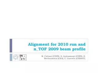
Alignment for 2010 run and n_TOF 2009 beam profile. M. Calviani (CERN), S. Andriamonje (CERN), E. Berthoumieux (CEA), C. Guerrero (CIEMAT),. Outline. Alignment campaign review for 2009 and 2010, summary of activities Activities in 2010 Update on the experimental beam profile.

E N D
Alignment for 2010 run and n_TOF 2009 beam profile M. Calviani (CERN), S. Andriamonje (CERN), E. Berthoumieux (CEA), C. Guerrero (CIEMAT),
Outline • Alignment campaign review for 2009 and 2010, summary of activities • Activities in 2010 • Update on the experimental beam profile • RESULTS AS OF APRIL 2010 • (n_TOF Collaboration Board 04/2010) • Complete set of analysis routine now freely available /afs/cern.ch/exp/ntof/XYMG • Analysis now responsibility of CEA M. Calviani - n_TOF Analysis Meeting CERN
Introduction – summary of 2009 observations • Measured neutron fluence during the 2009 run was ~20% less than expected (comparison with simulations and old official fluence) • n_TOF experimental beam profile misalignment of the 2nd collimator • 11% of fluence recovered in November 2009 tilt of ~2 mm of 2nd collimator (-8 mm upstr., -6 mm downstr.)! NB: the theoretical beam line (with which the 2nd collimator is aligned) has been defined by looking at the 1st collimator center -4, -4 = 0 mm -7, -4 = -3 mm -6, -4 = -2 mm -9, -4 = -5 mm -8, -4 = -4 mm • In 2010 the alignment has been performed by looking at the spallation target • 5 cm left radially(looking at target) to intercept the maximum of the fluence 0, -4 = +4 mm M. Calviani - n_TOF Analysis Meeting CERN
Alignment campaign 2010 • Surveyor’s theoretical beam line defined with the following steps: • A theodolite is placed in the Escape Lane (FIC2 place), where fixed (2001) reference points are placed in the floor • Theodolite view is set to 0.67°proper inclination of the TOF line. For the radial direction, uses a reference in the EL • Observation: The center of the theodolite is very close to the mechanical center of the neutron window • Vertical ok • Horizontal is shifted by ~1 cm M. Calviani - n_TOF Analysis Meeting CERN
Alignment campaign 2010 • The 1st collimator is shifted up by 1.9 cm, left by 0.75 cm, looking to the target • No information on the possible tilt • Explains the 2009 movements on the 2nd collimator • ~9% decrease in fluence from the simulations • Movement possible but not easy (not foreseen for now) • NB: this shift was always in place, since the construction of the facility! • 2010 Alignment will be performed by looking: • Vertically mechanical center of the window • Radially 5 cm to the leftof the mechanical center • New reference points will be established in the EAR-WS M. Calviani - n_TOF Analysis Meeting CERN
2010 plans on alignment • First measurements included the movement of the 2nd collimatorto try maximizing the fluence • vertical movement only • horizontal movement available but too risky for the moment (possible if beam profile show a significant horizontal skew) • SiMon + XYMG with 10B or 235U sample • simultaneous profile and fluence variation evaluation • borated water (*) CEA data • 235U will allow to have a reasonable statistics in the HE part • XYMG current routine (v. 2.8/2.9) limited by a significant dead-time (signal is ~200 ms long) X-Y MicroMegas Silicon Monitor Monitoring MGAS M. Calviani - n_TOF Analysis Meeting CERN
n_TOF Collaboration Meeting 2009 X-Y MicroMegas for n_TOF (1/2) • Application for monitoring of the n_TOF neutron beam • Neutron beam profile from thermal up to ~1 MeV • Detector used for helping in the alignment of the experimental area • experimental (almost real-time) position of the neutron beam • Detector based on the “bulk” technique • Active region is separated in two active regions: • conversion (drift) 480 V • amplification (mesh) gap 330 V • Anode segmented into 106 strips for each X and Y pad (tilted 90 deg.) M. Calviani - n_TOF Analysis Meeting CERN
n_TOF Collaboration Meeting 2009 X-Y MicroMegas for n_TOF (2/2) • 60 mm x 60 mm with 106 strips per pad 566 mm pitch • 212 channels too much for fADC two multiplexer card based on Gassiplex concept have been used 2 output directly to the n_TOF fADC • Trigger signal is available through the mesh signal • n_TOF available Gassiplex is able to read only 96 strips (reduced active area) • DAQ and analysis routine have been specially developed • Operation principle: • Read consecutively all the X and Y strips • 2 ms per strip total of ~192 ms • dead-time issues if the count rate is too high (but non-paralyzable) • Neutron converter, enriched 10B4C, deposited by sputtering on a 3 cm radius on a coppered (1mm) kapton (12.5 mm) substrate. • thin ~ 24 nm thickness (no dead-time) • thick ~ 2 mm thickness (for the high energy part) M. Calviani - n_TOF Analysis Meeting CERN
n_TOF Collaboration Meeting 2009 X-Y MicroMegas Analysis procedure (1/2) • Digitized Gassiplex signals are the input of the analysis • Each mesh signal trigger the aperture of a gate of 192 ms wide (T/H) • In order to record MeV neutrons, the prompt flash is remove “by hardware” in the Gassiplex trigger stage 192 ms • Pedestal runs are needed to evaluate mean value of the signal is each of the strips • + level shift Amplitude distribution of signals after pedestal subtraction and level shift correction (+/- 2 channels baseline) M. Calviani - n_TOF Analysis Meeting CERN
n_TOF Collaboration Meeting 2009 X-Y MicroMegas Analysis procedure (2/2) • Cluster analysis used to search for strips that have fired above the mean value of baseline (> 10 ch above baseline with >= 1 fired strip) • “Center-of -charge” applied to define the interaction point • Coincidence method to reconstruct a 2D image of neutron beam • # fired strips >1 • rotation of 225 deg. to obtain image as of neutron beam • energy selection based on TOF M. Calviani - n_TOF Analysis Meeting CERN
X-Y MicroMegas 2009 results up to 1 keV Fit on data performed on the base of a gaussian + step function 1 eV – 1 keV • Simulation assuming perfect alignment • Simulations assuming -2 mm tilt upstream 2nd collimator th. - 1 eV th. - 1 eV 1 eV – 1 keV Assumed tilt is in agreement to what has been found during the 2nd collimator alignment tests M. Calviani - n_TOF Analysis Meeting CERN
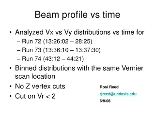
Updates on the experimental beam profile 2009 with XYMG 100 keV – 1 MeV Vertical Horizontal M. Calviani - n_TOF Analysis Meeting CERN
X-Y MicroMegas 2010 results • Beam profile run 10099-10101: • Main observations: • beam profile seems to be symmetric effectiveness of 2nd collimator alignment • data at higher energy mainly limited by statistics (with analysis routine v2.9 (the latest by MC)) improved by updates by CEA M. Calviani - n_TOF Analysis Meeting CERN
Analysis routines • Freely available (source included) at /afs/cern.ch/exp/ntof/XYMG • Detailed description of the routines can be found on http://cdsweb.cern.ch/collection/n_TOF%20Internal%20Notes?ln=en as a private Internal Note (accessible to members of the ntof-runs@cern.ch e-group • X-Y MicroMegas analysis: how to run the programs, n_TOF-INT-2010-002, July 2010 • New 2D MicroMegas detector for n_TOF beam profile: description and preliminary results, n_TOF-INT-2010-001, July 2009 • Now CEA has taken over the work and implemented the suggested improvements • namely the integration of the mesh signal in the analysis, which will lead to an improved statistics • better calibration especially at higher energies M. Calviani - n_TOF Analysis Meeting CERN
For the future if needed: proposal for 1st collimator Needs for the 1st collimator: Understand if tilting is present (it may affect significantly the fluence) Consider the possibility to shift it down into the proper location Shifting Tilting • We can measure it with the help of a planar laser, similarly to what we did for the 2nd collimator • it requires some work and still an uncertainty of 1-2 mm is to be taken into account • Action complex by the fact that it requires lifting an heavy piece • The downstream part is fixed into the wall • The upstream part can be moved down • removal of the filter station • adjustment of the TOF line Filter station downstream upstream 1st collimator NB: geometer’s independent action M. Calviani - n_TOF Analysis Meeting CERN
Conclusions • n_TOF beam line up to the Experimental Area is aligned by looking at the spallation target neutron window • 2nd collimator is aligned accordingly • 1st collimator is shifted/tilted, no easy way to move it back to proper position its effect on the flux reduction account to few % • Review of the XYMG analysis as performed in 2009 and beginning of 2010 • Status of the analysis routines • Good agreement with simulated beam profile • Indications on the misalignment of the 2nd collimator • Predictions have been verified experimentally could be used for alignment purposes M. Calviani - n_TOF Analysis Meeting CERN
End M. Calviani - n_TOF Analysis Meeting CERN
Evident misalignment of the 2nd collimator upstream bellow ~ 1 cm (?) Upstream bellow April 2009 Dowstream bellow Results after the optimizations Upstream bellow November 2009 also April 2010 M. Calviani - n_TOF Analysis Meeting CERN
Only 96 strips are read over a total of 106 (effect on beam position) M. Calviani - n_TOF Analysis Meeting CERN