### Innovative Super-Module Design for High-Performance Particle Detection Systems ###
This document outlines the architecture and functionality of an advanced Super-Module designed for particle detection applications. With a barrel length of 241.4 cm and a 120 cm Super-Module length, the system integrates double-sided modules featuring multiple ASICs for efficient data processing. The design includes a complex interplay of modules, hybrid configurations, and a Super-Module Controller (SMC) to manage readout links effectively. Key components are optimized for latency, allowing seamless operation in high-speed environments, crucial for modern particle physics experiments. ###

### Innovative Super-Module Design for High-Performance Particle Detection Systems ###
E N D
Presentation Transcript
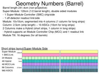
Geometry Numbers (Barrel) Barrel length 241.4cm (non-projective) Super-Module: 120cm (1/2 barrel length), double sided modules • 1 Super-Module-Controller (SMC) chip/side • 1 off-detector readout link/side Module: 10x10cm, segmented into 4 columns (1 column for long strips) Column: 2.5cm (strip length) – 10 ASICs (10cm for long strips) 2 Columns make a Hybrid (short strips, 1 column in long strips) - Hybrid supports an Module Controller Chip (MCC) and 1 readout link Module Tilt: 16 degrees (for all barrels) Short strips layout/Super-Module Side Super-Module 1 SMC/Link 24 Module 48 Hybrid 48 MCC/Link 96 Columns 960 ASICS 120cm 10cm 5cm 2.5cm
Event Data Flow Super-Module (Stave) A Super-Module (= Stave) comprises • 2 Sides A Super-Module Side • 12 Modules (= Wafers) • 1 Super Module Controller (SMC). A Module comprises • 1 Wafer (4x2.5mm strips or 1x10mm strips) • 2 Hybrids A Hybrid comprises • 2 Columns of 10 ASICs (1 for long strips) • 1 Module Controller Chip (MCC) driving a point-to-point readout link to the SMC (Cu, 160Mb) Module / Wafer Module / Wafer Hybrid Hybrid Hybrid Hybrid x12 MCC MCC MCC MCC MCC Links x24 SMC/ GBT x944 (Barrel) The SMC aggregates 24 MCC links (12 or long) into 1 GBT link connected to a ROD (fibre, 3.84Gbs) Channels per ROD are unknown, but ~20 likely, considering current rack space allocation – 4x 9U crates for the barrel = 240 channels/crate. 240/12=20 for ATCA. 240/16=16 for VME ROD ROD channel ROD channel x20
Module 31.4mm 24mm 24mm MCC 6.2mm 5mm SENSOR 97.6mm 5mm 6.2mm Power/DCS Ashley Greenall, Liverpool
L0A Flow 1: BC → SMC Presumed that L0A arrives at all MCCs synchronously, a fixed time after the BC. • Muon and/or Calo triggers ~1500ns • RoI identify CAM ~25ns • ID/s passed to RoI Mapper (RoIM) 16b/RoI ~100ns • RoIM maps ID to ROD channels (via geometry) CAM ~25ns - Important step for latency – removes all virtual info – connections only - Modules/MCCs on a SM bit-mapped to L0A Word (1bit per MCC) • RoIM sends L0A Words to RODs on p-t-p links 24b/ROD ch. ~100ns - Fibre optic 160bits/100ns, parallel Cu even faster • ROD forwards L0A Word to SMC 24b/SMC ~100ns - Need to ‘break into’ stream – additional latency? - Use only 1 GBT word (80bits, 25ns+75ns? overhead) - Multiple SM’s could share a single control link: x16=+200ns latency TOTAL: 1850ns (+500ns fibre length) 1500ns 100ns 100ns 50ns 25ns 25ns 50ns 1 2 3 4 5 6 USA15 SM ROD SMC SM SM Muon Trigger SM SM RoI ID RoI → ROD Channel Mapper SM ROD SMC SM SM SM SM Calo Trigger SM ROD SMC SM SM SM SM
L0A Flow 2: SMC → MCC The SMC needs to target an L0A to each MCC over 40Mb link/s. The current design has commands broadcast to all MCCs on 1 line. Latency = 25ns*(24b L0A Word+4b Header) = 700ns!! Note: This presumes L0 granularity at MCC level Various options are available to reduce latency: • Divide the SM into command zones - More tracks + Reduces latency to 25ns* (e.g 3 zones = 8b L0A Word+4b Header) = 300ns • Dedicated L0A broadcast line (no header) - One more track + Reduces latency to 25ns*24b = 600ns • Point to point dedicated L0A lines - 24 extra conductors on SM + Latency = 25ns • A few dedicated L0A links (e.g. 6x4 L0A lines) – Good compromise - More tracks + e.g. 4 MCC/L0A line = 25ns*4b = 200ns • Use faster clock! In all cases the contribution of the SMC is ~25ns as the reset of the link (GBT) latency is already accounted for. Possible TOTAL: 200ns SMC MCC MCC MCC
MCC L0A Processing Latency Note: L0 granularity is at the MCC level - all transfers from MCC to SMC are at 160Mb/s, but 2 columns = 80Mb/s/column L0A (or L0A word) arrives at MCC “L0/STOP” signal sent to all ASICs to pause L1 event sending 2) MCC waits required time for ASICs to stop sending data - ~25ns 3) MCC sends a special event-split trailer (aka L0-header) to tell downstream that the existing transfer has been interrupted for L0 event transfer. 17b=212.5ns 4) MCC send BCID (4b) 50ns small as we don't have a readout-buffer to confuse us 5) MCC sends L0ID (2b) 25ns can be even smaller as only sequence is important 5) Real L0 data arrives from ASICs, passes through MCC 25ns 6) Add latency due to data packet. 100 bits 1250ns 7) Trailer appended, (may not affect latency as lengths are known) 212.5ns The L0/STOP is de-asserted such that ASICs resume sending in phase. TOTAL: 1587.5ns (1800ns)
ASIC Processing • Receives L0/STOP signal • Starts L0 state-machine (processing done while MCC sends L0-header ~8 Bx = 200ns available) • pulls data from pipeline • Removes big clusters, small clusters to single bit hits • Counts hits • Finds 1st hit, encodes • Finds 2nd hit, encodes • Finds 3rd hit, encodes • Twiddles thumbs • Twiddles some more (waits for token) Note: Some of the above could be done while sending, could also be done at 2xBx too… i.e. This is not a bottleneck!
L0 Data Path: MCC → Track Finder From the MCC off-detectorwards L1 and L0 are a single stream. • Although each SM has a single fibre, the GBT essentially provides a point-to-point link from MCC to ROD sub-channel MCC => SMC -> ROD channel => ROD sub-ch => L0-out => Track-Finder • ROD watches raw stream looking for L0-headers - when found it pauses filling it's usual data FIFOs and diverts the stream to the trigger output. • Ideally the links are the same GBT used by SMC/ROD - Same bandwidth/MCC (no buffering/latency) - In track-finder MCC location preset (i.e. data on a virtual-link is always from same MCC). - Synchronous - No ID’s – the link IS the MCC • Efficient link use is the question… - Data volumes are far lower, so a full GBT seems wasteful - As we know only a fraction of a SM readsout L0 data (this can be enforced upstream at the L0 generation layer) we could combine SMs onto a single GBT. BUT this needs ‘routing’ – channel ID’s pre-pended to data Say 4x reduction = 2 bits extra, no big deal, but the multiplexing could be a pain (latency/debug) TOTAL latency is 100ns + 500ns cable delay
TOTAL Latency • BC → SMC 1850ns • SMC → MCC 200ns • MCC (and ASICs) 1600ns • MCC → Trackfinder 600ns TOTAL 4250ns