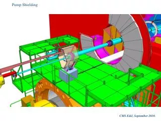
Efficient Shielding Design for Endcap Beam Pipe Protection in Maintenance Areas
This document outlines the design goals for an endcap shielding system aimed at protecting maintenance workers from radiation exposure during pipe maintenance. An estimated thickness of 2 cm of lead (Pb) will weigh approximately 2.5 tonnes, making it easy to install while effectively shielding workers. The design ensures that maintenance tasks on adjacent chambers remain unimpeded, with specific emphasis on securing the beam pipe against falling objects. The conceptual design is progressing towards detailed drawings, focusing on Pb-free installation and weight comparisons with existing shielding designs.

Efficient Shielding Design for Endcap Beam Pipe Protection in Maintenance Areas
E N D
Presentation Transcript
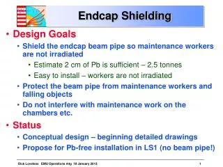
Endcap Shielding • Design Goals • Shield the endcap beam pipe so maintenance workers are not irradiated • Estimate 2 cm of Pb is sufficient – 2.5 tonnes • Easy to install – workers are not irradiated • Protect the beam pipe from maintenance workers and falling objects • Do not interfere with maintenance work on the chambers etc. • Status • Conceptual design – beginning detailed drawings • Proposefor Pb-free installation in LS1 (no beam pipe!)
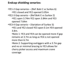
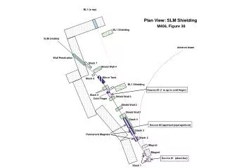
Length and weight comparison of YE1-YE2 shielding and YE2-YE3 shielding YE1 closed and YE2 at 3.05m Physical gap is 2556mm YE2 at 3.9m and YE3 at 7.64m (delta 3740) Physical gap is 3673mm This view represents length but not shape of shielding 2500 KG of lead only 1290 kg estimated total
YE1/2 shielding assembly retracted with clam shells open Lead half cylinders
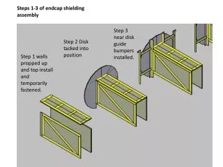
Step 1 shielding assembly is lowered into guide pins Estimated lead weight is 1000kg Guide pins ME2 ME3
Mounting and guidance concept Guide rods extend out 200mm from the spacer ring Permanent shielding mounts provide horizontal surface for feet to rest
Mounting of guide rod Flange on pin rod Quick release pin inserted here
Step 2 Assembly is lowered until it is low enough for extension into the spacer rings
Step 3 assembly is extended into the spacer rings and the load is transferred from the crane to the spacer rings
Step 5 feet are secured Lips to constrain location
Draft model of YE2/3 assembly in gap 20mm of lead weighs 3600 kg
End view of shielding assembly Shielding clam shells in the open position
Assembly without motor drive actuators. Uses crane to lower clam shell halves after the frame sets down.