CAMS
CAMS. lgmotorsports.com. Animation by Seán Douglas. Crossection of a cylinder head showing the DOHC (Double OverHead Cam), followers and valves. http://en.wikipedia.org/wiki/File:DOHC-Zylinderkopf-Schnitt.jpg. Knife follower. Foll. Harmonic motion cam. CAM FOLLOWER TYPES.


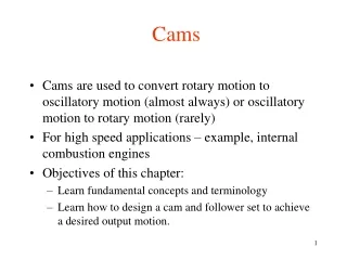
CAMS
E N D
Presentation Transcript
CAMS lgmotorsports.com
Crossection of a cylinder head showing the DOHC (Double OverHead Cam), followers and valves http://en.wikipedia.org/wiki/File:DOHC-Zylinderkopf-Schnitt.jpg
Knife follower Foll Harmonic motion cam
CAM FOLLOWER TYPES http://arab-training.com/vb/t6743.html
FLAT FOLLOWER http://arab-training.com/vb/t6743.html
ROLLER FOLLOWER http://arab-training.com/vb/t6743.html
KNIFE FOLLOWER http://arab-training.com/vb/t6743.html
Insert the page under the clip, making sure it is touching the stops.
DESIGN A CAM SPECIFICATIONS: SHAFT DIAMETER………..20mm MINIMUM DIAMETER….40mm LIFT……………………………...40mm PERFORMANCE…………….SIMPLE HARMONIC MOTION FOLLOWER…………………...KNIFE ROTATION……………………CLOCKWISE These are the specifications for the cam which will now be constructed.
12 spaces of 15mm 50 40 150 Measure 150mm from the bottom border, plus 40mm. Draw 2 light horizontal lines as shown. Measure 50mm from the clip, then mark 12 spaces of 15mm.
20 Draw light vertical lines from each of the 15mm marks along the horizontal line. Measure 20mm up the first vertical line on the left side.
Draw a semi-circle of radius 20mm from the 20mm mark on the first vertical line, as shown. Using set squares, divide the semi-circle into 6 radial segments of 300, as shown.
SIMPLE HARMONIC MOTION From the intersection of each of the radial lines and the semi-circle, draw light horizontal lines across the drawing, as shown. Draw the harmonic motion line as shown across the diagram. This represents the motion of the cam.
80 RISE 20 SIMPLE HARMONIC MOTION Measure 80mm from the right margin and draw a vertical line. Measure 20mm down from the bottom horizontal line and draw another horizontal line. The 20mm represents the minimum radius of the cam. Neatly print the word RISE between the two horizontal lines.
RISE SIMPLE HARMONIC MOTION SHAFT DIA 20 MINIMUM DIA 40 At the two intersecting lines, draw a 20mm diameter circle to represent the cam shaft. Draw a 40mm diameter circle to represent the minimum diameter of the cam. Following the lines around, mark as shown.
2 3 4 5 6 10 11 12 1 1 7 8 9 1 12 2 RISE 3 11 SIMPLE HARMONIC MOTION 10 4 9 5 6 8 7 Using set squares, draw radial lines and number them in the order as shown.
2 3 4 5 6 10 11 12 1 1 7 8 9 1 12 2 RISE 3 11 SIMPLE HARMONIC MOTION 10 4 9 5 6 8 7 Draw horizontal lines from the graph to the vertical line which passes through the circle. From the centre of the camshaft, draw circles where their radii are the distances from the centre to the respective horizontal lines.
2 3 4 5 6 10 11 12 1 1 7 8 9 1 12 2 RISE 3 11 SIMPLE HARMONIC MOTION 10 4 9 5 6 8 7 At the two intersecting lines, draw a 20mm diameter circle to represent the cam shaft. Draw a 40mm diameter circle to represent the minimum diameter of the cam. Following the lines around, mark as shown.
2 3 4 5 6 10 11 12 1 1 7 8 9 1 12 2 RISE 3 11 SIMPLE HARMONIC MOTION 10 4 9 5 6 8 7 At the two intersecting lines, draw a 20mm diameter circle to represent the cam shaft. Draw a 40mm diameter circle to represent the minimum diameter of the cam. Following the lines around, mark as shown.
2 3 4 5 6 10 11 12 1 1 7 8 9 1 12 2 RISE 3 11 SIMPLE HARMONIC MOTION 10 4 9 5 6 8 7 At the two intersecting lines, draw a 20mm diameter circle to represent the cam shaft. Draw a 40mm diameter circle to represent the minimum diameter of the cam. Following the lines around, mark as shown.
2 3 4 5 6 10 11 12 1 1 7 8 9 1 12 2 RISE 3 11 SIMPLE HARMONIC MOTION 10 4 9 5 6 8 7 Join the dots with a smooth line to represent the shape of the Harmonic Motion Cam.
2 3 4 5 6 10 11 12 1 1 7 8 9 1 12 2 RISE 3 11 SIMPLE HARMONIC MOTION 10 4 9 5 SHAFT DIAMETER 6 8 MINIMUM CAM DIAMETER 7 CAM PROFILE YEAR 9 HARMONIC MOTION CAM DESIGN NAME DATE NUMBER Join the dots with a smooth line to represent the shape of the Harmonic Motion Cam. Add notes and complete the details in the title block.
2 3 4 5 6 10 11 12 1 1 7 8 9 1 12 2 RISE 3 11 SIMPLE HARMONIC MOTION 10 4 9 5 6 8 7 This is the action of the cam that has been drawn.
Check that the drawing is neatly presented, that construction lines have been removed and that your name is on the drawing. It may now be submitted for assessment. Produced for use at St. Patrick’s College Launceston by John C Douglas, October 17, 2010.