Download

1 / 27
410 likes | 1.09k Vues
Gears and Cams. Chapter 17. Objectives. Define the characteristics of a spur gear, worm gear, and bevel gear Calculate the gear ratio and rpm of two mating gears, given the pitch diameters Define the principal spur gear terms Draw a spur gear. Objectives (cont.).

E N D
Gears and Cams Chapter 17
Objectives • Define the characteristics of a spur gear, worm gear, and bevel gear • Calculate the gear ratio and rpm of two mating gears, given the pitch diameters • Define the principal spur gear terms • Draw a spur gear
Objectives (cont.) • Describe the relationship between a cam profile and a displacement diagram • Draw a cam profile, given a displacement profile drawing • List the types of cam followers
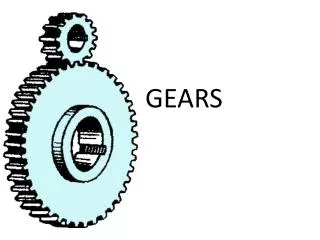
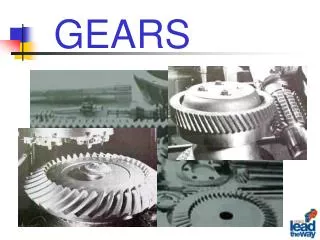
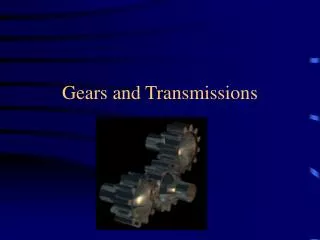
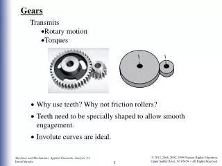
Understanding Gears • Gears are used to transmit power and rotating or reciprocating motion from one machine part to another • ANSI/AGMA publishes detailed standards for gear design and drawings
Spur Gears • Proportions and shapes of gear teeth are well standardized • The most common geometric form used in gears today is the involute profile • Involute means “rolled inward”
Spacing Gear Teeth • Teeth are spaced around the periphery by laying out equal angles • The number of spaces should be twice the number of teeth, equal to the tooth thickness at the pitch circle
Rack Teeth • Gear teeth formed on a flat surface are called a rack
Working Drawings of Spur Gears • Since teeth are cut to a standard shape, individual teeth are not typically shown
Spur Gear Design • Spur gear design normally begins with selecting pitch diameter • The size of the teeth (diametral pitch) depends on: • Gear speeds • Gear materials • Horsepower to be transmitted • Tooth form
Worm Gears • Worm gears are used to transmit power between nonintersecting shafts that are at right angles to each other • A worm is a screw with a thread shaped like a rack tooth • Worm wheels are similar to helical gears cut to conform to the shape of the worm
Working Drawings of Worm Gears • In assembly drawings, gear teeth are omitted and the gear blank represented conventionally • On detail drawings, the worm and gear are usually drawn separately
Bevel Gears • Bevel gears transmit power between shafts whose axes intersect at any angle • Bevel gear teeth have the same involute shape as teeth on spur gears but are tapered toward the cone apex
Working Drawings of Bevel Gears • Working drawings for bevel gears give only the dimensions of the gear blank • Data necessary for cutting teeth are given in a note or table
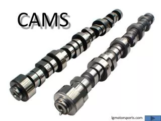
Cams • Cams can be used to produce irregular motions • A shaft rotating at uniform speed carries the cam • A reciprocating member, called the follower, presses a roller against the curved surface of the cam • Rotating the cam causes the follower to reciprocate a cyclic motion according to the cam profile
Displacement Diagrams • A displacement diagram is a curve showing the displacement of the follower as ordinates on a base line that represents one revolution of the cam • The motion of the follower as it rises or falls depends on the shape of the curves in the displacement diagram
Cylindrical Cams • When the follower movement is in a plane parallel to the cam shaft, a cylindrical cam must be employed