Download
1 / 27
270 likes | 472 Vues
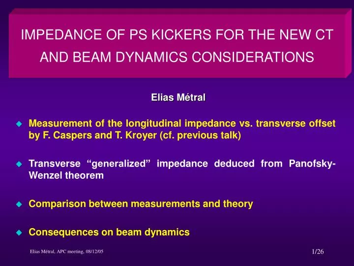
IMPEDANCE OF PS KICKERS FOR THE NEW CT AND BEAM DYNAMICS CONSIDERATIONS. Elias Métral. Measurement of the longitudinal impedance vs. transverse offset by F. Caspers and T. Kroyer (cf. previous talk) Transverse “generalized” impedance deduced from Panofsky-Wenzel theorem

E N D
IMPEDANCE OF PS KICKERS FOR THE NEW CT AND BEAM DYNAMICS CONSIDERATIONS Elias Métral • Measurement of the longitudinal impedance vs. transverse offset by F. Caspers and T. Kroyer (cf. previous talk) • Transverse “generalized” impedance deduced from Panofsky-Wenzel theorem • Comparison between measurements and theory • Consequences on beam dynamics
INTRODUCTION (1/3) • The following kickers are installed presently in the PS machine • Injection kicker in section 45 • Extraction kicker in sections 71 and 79 • BFAs (pedestal and staircase) in sections 9 and 21 • Injection kicker for ions in section 28 • The following kickers will be installed for the first stage of the novel multi-turn extraction • Two new kickers in sections 13 and 21. The modules are similar to those of the extraction kicker • One new kicker in section 4. The modules are recuperated from the extraction kicker for leptons • All the kickers mentioned under the point 1. will be also present • For the second stage it is foreseen to • Decrease the rise-time of the kickers in section 13 and 21. At the same time a new design of the modules could be made so to reduce the impedance seen by the beam • The BFA in section 21 will be removed • The BFA in section 9 will stay in the machine • Injection kickers (section 28 and 45) and the extraction kicker (sections 71 and 79) will, of course, remain in the machine
INTRODUCTION (2/3) • Measured longitudinal impedance vs. transverse offset, using a single displaced wire (in a symmetric structure) The sum (or difference) of the dipolar (driving) and quadrupolar (detuning) impedances is measured with a single displaced wire This explains why very different results are measured with the 2-wire method (which measures only the dipolar impedance) and the single-wire method (where >0, 0, or <0 impedances can be measured)
INTRODUCTION (3/3) Longitudinal (classical) resistive-wall impedance (with a single wire) for a 2D rectangular metallic pipe of height 2b and width 2a • Example given by Tsutsui (CERN-SL-Note-2002-034 AP) This explains why a zero impedance can be measured in the horizontal plane of a flat chamber, with a single wire
Kicker 1 2 will be installed in the PS (SS 13 and 21) It is the same type as the extraction kicker KFA 71 (but 4 times smaller) The ferrite is split longitudinally in many cells Each cell is 24 mm long (19 mm of ferrite + 5 mm of Al)
Kicker 1 Measurements vs. Tsutsui (giving here only the driving) Tsutsui’s model Perfect conductor Im Re
Kicker 1 Comparison Tsutsui-Burov&Lebedev for the vertical driving impedance Measurements vs. Tsutsui Measurements vs. Burov-Lebedev
MEASURED LONGITUDINAL IMPEDANCE (Re) VS. HORIZONTAL OFFSET 100 pictures (every 10 MHz until 1 GHz)
MEASURED LONGITUDINAL IMPEDANCE (Im) VS. HORIZONTAL OFFSET 100 pictures (every 10 MHz until 1 GHz)
MEASURED LONGITUDINAL IMPEDANCE (Re) VS. VERTICAL OFFSET 100 pictures (every 10 MHz until 1 GHz)
MEASURED LONGITUDINAL IMPEDANCE (Im) VS. VERTICAL OFFSET 100 pictures (every 10 MHz until 1 GHz)
THE NEXT 4 SLIDES ARE THE SAME AS THE PREVIOUS 4 ONES, BUT WITHOUT A FIXED VERTICAL SCALE 100 pictures (every 10 MHz until 1 GHz)
Kicker 1 Measured horizontal + vertical driving impedances (as when we sum the measured transverse impedances the detuning impedance disappears) Im Re
Kicker 2 1 will be installed in the PS (SS 4) Modules recuperated from the extraction kicker for leptons The ferrite is split longitudinally in many cells Each cell is 24 mm long (19 mm of ferrite + 5 mm of Al)
Kicker 2 Measurements vs. Tsutsui (giving here only the driving) Tsutsui’s model Perfect conductor Im Re
Kicker 2 Comparison Tsutsui-Burov&Lebedev for the vertical driving impedance Measurements vs. Tsutsui Measurements vs. Burov-Lebedev
Kicker 2 Measured horizontal + vertical driving impedances (as when we sum the measured transverse impedances the detuning impedance disappears) Im Re
CONCLUSIONS FROM THE MEASUREMENTS • 2 kickers of type 1 (at large βx and small βy) + 1 kicker of type 2 (at small βx and large βy) will add to the PS machine • A longitudinal Broad-Band impedance of ~ 2 Ω, with a resonance frequency near ~ 400-500 MHz • A maximum (upper limit) transverse Broad-Band (driving) impedance of ~ 0.25 MΩ/m, with a resonance frequency near ~ 700 MHz. Taking into account the β’s leads to a normalized impedance of ~ 0.2 MΩ/m
COMPARISON WITH THE PS “MEASURED” IMPEDANCES • The (usual) Broad-Band impedances measured in the PS machine are • A longitudinal Broad-Band impedance of ~ 20 Ω, with a resonance frequency near ~ 1.4 GHz • A horizontal Broad-Band impedance of ~ 1 MΩ/m, with a resonance frequency near ~ 1.4 GHz • A vertical Broad-Band impedance of ~ 3 MΩ/m, with a resonance frequency near ~ 1.4 GHz The 3 kickers for the new CT will increase • The longitudinal impedance by ~ 10% • The transverse impedance by ~ 10%
CONSEQUENCES ON BEAM DYNAMICS (1/3) • Check longitudinal beam stability in particular for LHC beams Can only be done with measurements (S. Hancock) • The vertical plane is the most critical due to the fast vertical single-bunch instability observed at transition with high-intensity beams Will be more critical at transition for nTOF ,R,V signals Fast vertical single-bunch instability near transition (~ 6 GeV total energy) ~ 700 MHz Time (10 ns/div) Instability suppressed by increasing the longitudinal emittance to ~ 2.2 eVs The longitudinal emittance will have to be slightly increased. Still possible with the removal of some 200 MHz cavities?
CONSEQUENCES ON BEAM DYNAMICS (2/3) BBU THEORY BB resonator impedance 1st trace = turn 1 Last trace = turn 90 Every turn shown
CONSEQUENCES ON BEAM DYNAMICS (3/3) MEASUREMENTS IN 2000 BBU THEORY AFTER 90 TURNS (~ 200 μs) Seem very close except head and tail exchanged!!! It may start only for the maximum peak intensity, i.e. in the middle… Try to produce the same movie with measurements next year (as we did for the SPS fast instability at injection)
CONCLUSION • The installation of 3 kickers for the new CT will add ~10% to the longitudinal and transverse broad-band impedances of the PS machine • The 114 MHz RF cavities were removed from the PS machine during the 2000-2001 shutdown • The kicker tanks in SS72 and SS94 (for leptons) were removed from the PS machine on 7/1/2003 • The fully nominal LHC beam was produced before we removed the lepton kickers (S. Hancock’s talk at Chamonix 2003) These kickers were not too harmful for the (nominal) LHC beam production • Two 200 MHZ RF cavities have been removed from the PS machine during this long shutdown What is the reduction of the impedance? Will it be possible to increase the longitudinal blow-up if necessary? Should be OK!