Mechanical Seal Analysis
Mechanical Seal Analysis. Nicholas McDermott. Overview. Background Balanced vs. Unbalanced Design Variables Pressure Distribution Factor Spring Pressure Outer Pressure Shaft Speed Conclusions. Background.

Mechanical Seal Analysis
E N D
Presentation Transcript
Mechanical Seal Analysis Nicholas McDermott
Overview • Background • Balanced vs. Unbalanced • Design Variables • Pressure Distribution Factor • Spring Pressure • Outer Pressure • Shaft Speed • Conclusions
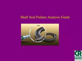
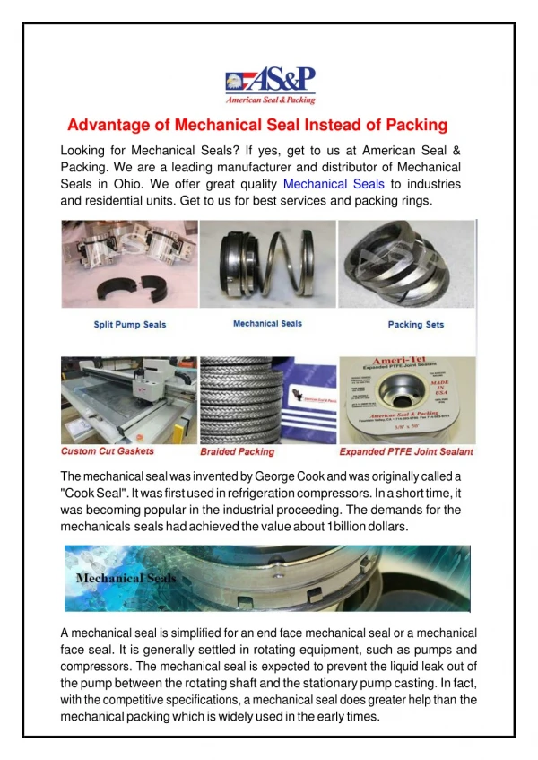
Background • A mechanical seal is used to prevent fluid from leaking in between the rotating shaft and the stationary housing. • The seal is ideally two opposing plane perpendicular to the shaft’s axis of rotation, forced together by a spring. • Mechanical seals’ primary advantage is a longer life span over gland packing seals. • Mechanical seals can operate in extreme environments and a variety of fluids. • Disadvantages are that the seals are more expensive and are more complex to design.
Background (Continued) • The mechanical seal operates in order to allow hydrodynamic lubrication to take place. • As a result it can be thought of as a controlled leakage, rather than a complete seal. • The allowable leakage rate is a compromise with the wear rate and life of the seal.
Balanced vs. Unbalanced Seals • The term of a balanced seal refers to the ratio of hydraulic area over the face seal area. A seal with the ratio greater than or equal to 1 is unbalanced. • Balanced seals have a greater face seal area reducing the pressure at the face compared to the hydraulic closing pressure. • Balanced seals are achieved usually by decreasing the shaft diameter at the sealing location. Making them more complex and more expensive than balanced seals, as a result they tend to be used in high pressure (1 – 7 Mpa) environments when unbalanced seals would wear too quickly.
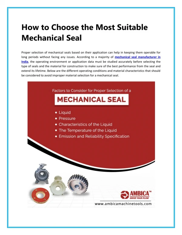
Design Variables • For the project four design variables were examined to see their effect on the leakage rate and the operational envelope of the seal. • The operational envelope is the area of pressure and fluid temperature combinations that the seal is safe to operate without causing the fluid to vaporize. If the fluid vaporizes the seal face will be subject to cavitation corrosion. • The four variables considered are the pressure distribution factor, the spring force/pressure, operating pressure, and the shaft speed.
Pressure Distribution Factor • Is the ratio of the average pressure between the seal faces and the pressure drop across the face. • It was initially assumed that the surfaces of the seal are parallel, separated my .5 micrometers and the pressure reduces linearly. This results in a pressure distribution factor (P.D.) of .5 • The best surface machining techniques can produce a flatness of 2.5 to 10 micrometers. • Because the surface imperfections is an order of magnitude greater than the thickness of the film, the pressure distribution factor can vary depending on the wear of the face seals.
Pressure Distribution Factor • The P.D. was explored for three variations of wear. The wear scenarios were run in COMSOL to see the P.D. variation
Pressure Distribution Factor • Based off of the results of the COMSOL models it was assumed that analyzing the seal varying the P.D. From .5 to .9 was reasonable. • The results is the greater the P.D. the lower the friction at the face and lower the temperature rise in the fluid. This is a result of the overall net closing force acting on the seal being reduced the greater pressure of the fluid.
Spring Pressure • The spring force affects the seal performance and the operational envelope. The correct spring force is a balance between the wear of the spring and the leakage rate. • To set a minimum spring pressure the scenario of the seal being blown open by the outer pressure difference should be considered. • There are two approaches to consider, the first is the seal is blown open, therefore the P.D. is equal to one. Given a spring pressure what is the minimum pressure difference that would cause the seal to blow open?
Spring Pressure • The table below shows the spring pressure and compares to the pressure difference that would cause the seal to blow open and the operating pressure of the seal. • The spring force has to increase dramatically to prevent the seal from blowing open, as a result the fluid film lubrication would not form, causing increased wear and shorter life of the seal. • This scenario is used when absolutely zero chance of the seal failing is required
Spring Pressure • The second scenario to consider for a minimum seal pressure is; what is the critical P.D. that would result in the seal blowing open? • Given the critical P.D. one has to weigh the risk of the P.D. getting to that point.
Spring Pressure • The maximum spring pressure that can be set is set to allow the film lubrication to form. If a parameter of delta P is the outer pressure minus the net closing pressure at the seal, when delta P is positive the fluid film lubrication will readily form.
Spring Pressure • As the spring pressure increases the temperature rise increases and the leakage rate decreases.