Download
1 / 28
300 likes | 497 Vues
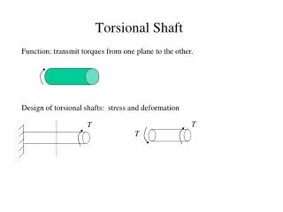
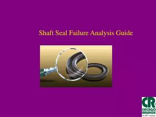
Shaft Seal Failure Analysis Guide.

E N D
Like any good detective, the time to start gathering clues is before anyone has disturbed the evidence. Just by looking at the environment -- judging the amount of dirt, grit or frequent wash-downs -- you can tell a lot about the possible causes of early seal failure. Then a step-by-step analysis will uncover other common causes. Sometimes the clues will be subtle, other times they'll be obvious. Armed with this guide, you should be able to unravel them all.
Cocked seal failureOne of the most common causes of early seal failure is a bad installation. Without the proper tool (or at least a soft tool spanning the seal diameter) the seal maybecome cocked in the bore. You may be able to see this before you even attempt to remove the seal.
Foreign matter on the seal caseIf the machinery has been painted without protecting the seal, the lip may be damaged. Also, oven drying the paint, or some paint solvents, can destroy the seal.Either remove the seal or mask the area well before painting.
Dents and DingsAn early leak is often the result of installing the seal without the proper tool. The evidence shows up as telltale marks on the seal shell. When an installation toolisn't available, a soft material, like wood, will work as long as it spans the seal.
No Chamfer on the boreThe beveled edge (chamfer) on the leading edge of the bore provides a ramp for starting the seal straight. Without it, it is virtually impossible to get the sealinstalled correctly. A 15-30° angle, clean and burr free, is recommended.
Burr DamageA deep scratch in the outer diameter that scribes a line across the seal width is usually the sign of a burr (or contamination) in the bore. This line creates a leakpath. Short, light scratch marks are usually the result of normal installation.
No Chamfer on the ShaftThe beveled edge ( or chamfer) at the end of the shaft provides a ramp for the seal to ride up on. Without it, the seal lip cannot be installed without beingdamaged or torn, as shown here. The lead-in chamfer must be smooth and burr free.
Torn LipAnother way for the sealing lip to be damaged is by attempting to install it over unprotected threads, splines or keyways. Adhesive tape, or Mylar tape,wrapped carefully around the shaft will usually provide enough protection to mount the seal successfully.
Heat DamageWhen operating speeds increase, seal lip temperatures may soar. One indication of high heat is a dry, brittle lip. Flexing the lip may reveal fine axial cracksaround the entire circumference. Another indicator is a thin band of carbonized oil along the seal lip that results when heat causes the lubricant to break-down.
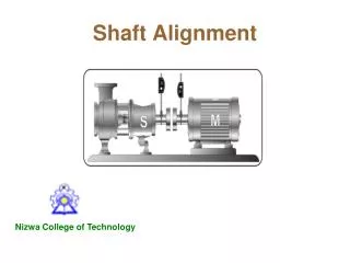
Shaft To Bore MisalignmentMisaligned components in a power train create Shaft To Bore Misalignment (STBM) and leaks. The cause may be machine inaccuracies or worn bearings,among other things. The seal lip will appear worn on one side and relatively untouched on the other. Shaft alignment should always be checked before installinga new seal.
Dynamic Run Out Dynamic Run Out is the result of a bent or unbalanced shaft. In such a condition the shaft does not rotate around its true center. The sealing lip will be severelyworn around the entire diameter. A dial indicator attached to the bore or housing while the shaft is rotated through 360° will reveal DRO.
Foreign MatterNothing but lubricant should come in contact with the sealing lip. In this instance, too much bore sealant was applied and was forced into the seal housing. Asthe sealant dries it hardens on the lip and causes the seal to fail.
Manufacturing DefectsAlways inspect a new seal before installing it. While process controls have nearly eliminated manufacturing errors, not every seal maker uses them. Here, theseal lips were destroyed during the molding process.
Pressure WearA heavily worn or scuffed path on the air side of the seal lip may indicate pressure build-up in the sump. Generally, shaft seals are designed to handle only light pressure. Each application should be properly vented to allow heated air to escape. In this example the sealing material has been worn so thin that the spring is showing through.
Dirt and GritTraces of metal particles or sand on the inner seal surfaces point to some type of internal contamination. An improperly cleaned casting will eventuallycontaminate the seals, as will failing gears or bearings. These residues collect in the spring area.
Chemical SwellingSome chemicals, including some lubricant additives, cause sealing materials to swell and soften. Dirt and grit particles can become embedded and the lip wearsrapidly. Changing from mineral to synthetic lubes can cause this problem.
DebondingLip materials are bonded, or held in place, in a variety of ways. Chemicals that are incompatible with the lip material or bonding agent can cause the seal toliterally come apart.
Deformation -- before and after --Incompatibility between the lip material and the operating media, including lubricants, can produce major swelling of the seal material. Above is a before andafter example of the gross damage you may see from chemical incompatibility.
Damaged SpringThe garter spring should be inspected for kinks or other damage. Springs can be damaged during installation or by rough handling. A damaged spring willproduce an out-of-round condition and create a leak at the seal lip.
No SpringPeople have been known to remove the garter spring in order to make installation easier. That it does. But it also reduces the effectiveness and life of the seal.The spring can also be lost through rough handling before or during installation.
Wrong Part NumberThis mistake is easy to overlook. The seal should be checked against specifications for both size and type. Also the size of the bore and the shaft should bemeasured accurately with a micrometer. And it should be noted whether the hardware measurements are in inch or metric sizes. The tolerances are different foreach.
Backwards installationMake sure that the seal lip is facing in the correct direction. Mark the outer case before removing the seal, and then check the direction of the lip. Shown aboveis a seal facing the wrong way to retain lubricant. It may be installed backwards intentionally where excluding contamination is most important.
When installing a shaft seal, the lip should be facing the medium to be contained. In this illustration the seal lip is "facing" backwards so that the lip is facing away from the grease lubricant. This is done when holdingout contamination is the most important job. Where there's room, two seals can be installed facing in opposite directions. One facing in to contain lubricant and the other facing out to increase protection against contamination. There are special back-to-back seals for this function that are described later on.
Shaft Preparation A burr-free chamfer or radius is required as illustrated here. (C = chamfer depth). The chamfer acts as a ramp for the sealing lip to ride up on. Without it, it is virtually impossible to install the seal without damaging the lip. Some manufacturers, in reducing production costs, have begun to produce shafts without a chamfer. They then use a special funnel-shaped tool to install the seal without damage. When replacing a seal on this type of shaft, you should first grind a smooth 15° to 30° chamfer.
Bore Preparation The lead corner, or entering edge, of the bore should be chamfered (as shown below) and free of burrs. The inside corner of the bore should have a maximum radius of .031" (0.79 mm).
Machine Lead The surface of a shaft, especially a reconditioned one, may contain a nearly (or actually) invisible screw-like pattern that augers lubricant under the seal lip.
The End for now Check out our website for more information http://www.chicago-rawhide.com/general/tech/tech.htm