Shaft Design
Shaft Design. Section VI. Talking Points. Shaft? Shaft Design ASME Shaft Equations Design of Shaft for Torsional Rigidity Standard Sizes of Shafts Bending and Torsional Moments. Shaft?. Rotating machine element that transmits power.

Shaft Design
E N D
Presentation Transcript
Shaft Design Section VI
Talking Points • Shaft? • Shaft Design • ASME Shaft Equations • Design of Shaft for Torsional Rigidity • Standard Sizes of Shafts • Bending and Torsional Moments
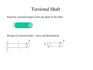
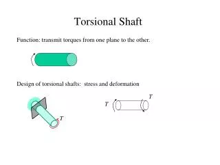
Shaft? • Rotating machine element that transmits power. • Shafts are usually circular in cross-section, and may be either hollow or solid.
Shaft Design • Design of shafts for ductile materials, based on strength, is controlled by the maximum-shear stress theory; while shafts of brittle materials would be designed on the basis of the maximum-normal stress theory. • Consists of the determination of the correct shaft diameter to ensure satisfactory strength and rigidity when the shaft is transmitting power under various operating and loading conditions. • Shafts are usually subjected to torsion, bending, and axial loads. 1) For axial loads: The tensile or compressive stress is: 2) For bending loads: The bending stress (tension or compression) is: 3) For torsional loads: The torsional stress is:
ASME Shaft Equations • The ASME code equation for hollow shaft combines torsion, bending, and axial loads by applying the maximum-shear equation modified by introducing shock, fatigue, and column factor as follows: • For solid shaft having little or no axial loading, the equation is: Where: Where:
Design of Shaft for Torsional Rigidity • It is based on the permissible angle of twist. The amount of twist permissible depends on the particular application, and varies about 0.3 degree/m for machine tool shafts to about 3.0 degree/m for line shafting. Where:
Standard Sizes of Shafts • These sizes vary according to material specifications and supplier. Typical sizes for solid shafts are: • Up to 25 mm in 0.5 mm increments • 25 to 50 mm in 1.0 mm increments • 50 to 100 mm in 2.0 mm increments • 100 to 200 mm in 5 mm increments
Bending and Torsional Moment • These are the main factors influencing shaft design. One of the first steps in shaft design is to draw the bending moment diagram for the loaded shaft or the combined bending moment diagram if the loads acting on the shaft are in more than one axial plane. From the bending moment diagram, the points of critical bending stress can be determined. The torsional moment acting on the shaft can be determined from: 1) For belt drive: The torque is found by: 2) For gear drive: The torque is found by: Where: Where: