DRIVE SHAFT
DRIVE SHAFT. Function, Construction and Operation. Drive Shaft Function -to transmit power from one point to another in a smooth, constinuos action. -In trucks and construction equipment,the drive shaft is designed to send torque through an angle from


DRIVE SHAFT
E N D
Presentation Transcript
DRIVE SHAFT Function, Construction and Operation
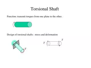
Drive Shaft Function -to transmit power from one point to another in a smooth, constinuos action. -In trucks and construction equipment,thedrive shaft is designed to send torque through an angle from the transmission to the axle( or auxiliarytransmission). -The drive shaft must operate through constantly changing relative angles the between transmission and axle. - it must also be capable of changing length while transmitting torque. - The axle of a vehicle is not attached directly to the frame, but rides suspended by springs in an irregular, floating motion.
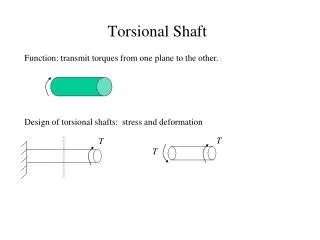
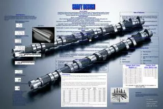
Construction of a Drive Shaft -To transmit required torque loads, the drive shaft must be durable and strong. Forged steel and high-strengrth, cast, end yoke for heavy-duty vehicles are used to provide the necessary rigidity required to maintain bearing alignment under torque loads. -Anti-friction bearings are used to with stand oscillating loads while the drive shaft is rotating at high speeds. The needle roller bearings on the cross trunnions carry large loads and are used because of their high capacity in a limited space. -Abrasive material is a major problem for vehicles operating in extremely moist and dirty environments. To Combat this problem, synthetic rubber seals were developed and resulted in increased life, ability to with stand high temperatures and a less critical relubrication cycle for drive shafts.
-Special high-strength tubing is used to provide maximum torque carrying capacrty at minimum practical weight. Drive shafts have been developed to meet the vehicular industry needs. -The slidingsplinesbetweenslip joint and permanent joint must support the drive shaft and be capable of sliding under full torque loads. -To aid in this axial or slip movement, Glidecote was developed to reduce sliding friction, reducing thrust under hightorque.This non-metalli coating also prevents spline galling and extends spline life.
Operation of Drive Shaft -Each shaft is installed in the same manner. A universal joint (Cardan type) and splined slip yoke are located at the transmission end of the shaft, where they are held in alignment by a bushing in the transmission rear extension. -The slip yoke permits fore and aft movement of the driveshaft as the differential assembly moves up and down. The spline is lubricated internally by transmission lubrication or grease. An oil seal at the transmission prevents leakage and protects the slip yoke from dust, dirt and other harmful material . -From some automatic transmissions, the slip yoke spline is lubricated with grease and provided with a small vent hole. The slip yokes should be inspected to be sure the vent hole is clear (Figure 19).
INSPECTING END FITTINGS Visually inspect all input and output end-fitting (yoke) retaining nuts, clips, or bolts for any gaps between mating surfaces. If gaps are present, consult transmission, axle or transfer case original equipment manufacturers’ service and maintenance manuals for proper fastener specifications. Try to move it vertically and horizontally to feel any looseness. (See photo left.) Listen for any clicking, or grinding noise from the joint. Take hold of the end fitting with both hands, rotate left to right, feeling for play or backlash (see photo left.) Listen for any clicking, or grinding noise from the joint. If radial looseness is evident, U-joints or yokes will have to be replaced.
. (See photo left above.) There should be less than .006 in. (.15mm) movement in the universal joint kit relative to the inboard or outboard yokes. If looseness is greater than .006 in. (.15mm), the universal joint kit must be replaced. INSPECTING UNIVERSAL JOINTS • Type • 1.Relubable style • 2.Permanently Lubricated Plug Style • 3.Permanently Lubricated Net-Formed Style
Reubable style Check for the presence of all grease zerk (nipple) fittings. (See photo left). Grease zerk (nipple) fittings should not be missing, loose or fractured. Permanently Lubricated Plug Style Permanently lubricated plug style universal joint kits do not contain grease zerk fittings, only a plug. (See photo left) Make sure plug is not missing, loose or fractured. If the plug is loose, tighten to required specifications. Permanently Lubricated Net-Formed Style Net-formed universal joints do not contain grease zerk (nipple) fittings or plugs and are not relubable (See photo left).
INSPECTING SLIP MEMBERS Check the slip member assembly for excessive radial looseness. (See photo left) If looseness is greater than .012 in. (.30mm) as read on dial indicator, replacement of the slip member assembly is necessary. For an inboard and outboard slip yoke assembly design, check to be sure the slip yoke welch plug is not loose, missing or damaged. (See photo left) If any of these situations are evident, replacement of the slip yoke and professional are balancing of the driveshaft is necessary. Visually inspect for the presence of the grease zerk fitting, if applicable, on the slip yoke. (See photo left) Grease zerk fittings should not be missing, loose or fractured.
Check the slip yoke seal. (See photo left) Make sure the seal is properly attached to the slip yoke and is not loose or damaged. If any of these situations are evident, replacement of slip member assembly is necessary. For permanently lubricated slip members, check yoke shaft boot (see photo left) or seal can. Make sure the boot or seal can is properly attached to the yoke shaft and tube sleeve and no damage or looseness is apparent INSPECTING TUBING Check the driveshaft for bent or dented tubing, cracks, or failed welds. If any of these situations is evident, replacement of the complete driveshaft assembly or tube is necessary.
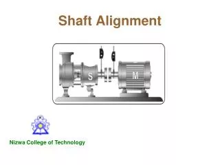
INSPECTING CENTER BEARINGS Visually inspect all center bearings, end-fitting midship nuts for any gaps between the mating surfaces. (See photo left) Be sure to repeat check for broken back and backlash.for all center bearing end fittings. Inspect the center bearing bracket bolts for looseness. (See photo left) If looseness is evident, are tighten center bearing bracket bolts. Check the alignment of the bracket before tightening the bolts. If any of these situations are evident, replacement of the center bearing assembly is necessary.