Shaft Alignment
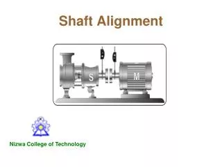
Shaft Alignment. Nizwa College of Technology. Shaft Alignment. Shaft alignment is the process to align two or more shafts with each other to within a tolerated margin. Shaft in Alignment. Types. Parallel or Lateral misalignment Angular misalignment

Shaft Alignment
E N D
Presentation Transcript
Shaft Alignment Nizwa College of Technology
Shaft Alignment Shaft alignment is the process to align two or more shafts with each other to within a tolerated margin. Shaft in Alignment Types • Parallel or Lateral misalignment • Angular misalignment • Combined Angular and Lateral misalignment Combined Angular and Lateral misalignment Parallel or Lateral misalignment Angular misalignment
Disadvantages of Misaligned shafts • When shafts are misaligned, forces are generated. • These forces are resulted in Vibration, noise, bearing damage, shaft damage, coupling damage and Looseness. • In extreme cases the bending stresses applied to the shaft will cause the shaft to fracture and break.
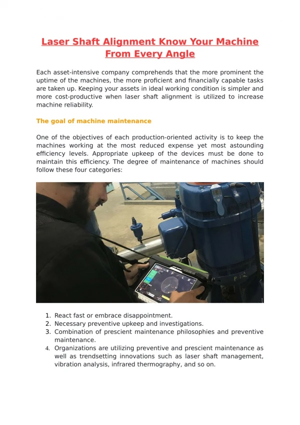
Shaft Aligning Techniques • Shaft alignment by conventional method • Shaft alignment by Dial Test Indicator (DTI) • Shaft alignment by Using LASER Equipment • Shaft alignment by using computer.
Shaft Aligning procedure • Preliminary Checks • Visually check coupling, pipe hangers, base bolts, coupling • spacing etc. • Check for coupling & shaft run out. • Sag Check • Clamp the brackets on a sturdy piece of pipe • Zero both indicators on top, and then rotate to the bottom. • The difference between the top and bottom reading is the sag • Each time alignment reading is taken then the sag must be • accounted for subtracting
Shaft alignment by Dial Test Indicator (DTI) Horizontal Alignment (Parallel) Motor Pump • Aligning the shaft's centerlines from side to side • The indicators are zeroed on the left and read at the right • Make sure that you always view the DTI from pump side • There is no sag compensation on the horizontal move • Record the indicator reading and move the motor to the required • distance for horizontal alignment.
Shaft alignment by Dial Test Indicator (DTI) Vertical Alignment (Angular) Motor Pump • The indicators are zeroed on the top and read at the bottom • Record the indicator reading and consider the sag compensation by • subtracting it from the recorded reading • Move the motor to the required distance for vertical alignment by • adding shims in place • Tighten all bolts and take and check the readings • If the readings are within tolerance than the equipment is aligned
Principle of Alignment (DTI) Arrangement of DTI in Alignment Vertical (Angular) Horizontal (Parallel)
Shaft alignment by Using LASER Equipment Lay out of Laser Alignment Parallel or Lateral misalignment Angular misalignment
Shaft alignment by Using LASER Equipment Measuring head 1 Measuring head 2 Display unit
General lay out of LASER Alignment Technique Laser beam on the measuring head General Lay out
Alignment procedure (LASER) Vertical Alignment
Alignment procedure (LASER) Horizontal Alignment
Alignment procedure Aligning Motor to Pump LASER Aligning Display Unit Reading Shows Angular & Parallel Deviation
Aligning of Equipments Aligning Motor to gear box Aligning Engine to Alternator