MFT
MFT. MFT. MFT – WG7 Mechanics and cooling. Summary: Mechanics Overview of the MFT in ALICE. Description of the MFT. Description of a MFT detection plane. Environment of the MFT. Procedure and tools for MFT installation. Conclusion, discussion Cooling


MFT
E N D
Presentation Transcript
MFT MFT MFT – WG7 Mechanics and cooling • Summary: • Mechanics • Overview of the MFT in ALICE. • Description of the MFT. • Description of a MFT detection plane. • Environment of the MFT. • Procedure and tools for MFT installation. • Conclusion, discussion • Cooling • Thermal and fluidic studies on the MFT. • Preliminaries studies of the impact of cooling on the MFT barrel. • Next steps Jean-michel.buhour@subatech.in2p3.frITS-MFT common week 10-13 March 2014
MFT MFT The place of the MFT in ALICE cross section at the beginning of the project (11/2011) TPC ITS Beam pipe absorber MFT C side A side beam V0, T0, FIT? IP Disclaimer: the following presentation is mainly based on the MFT LoI with some modifications: 6th plane added, planes position versus IP modified
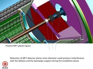
General view of the MFT in ALICE Sketch of integration MFT-ITS-FIT-BP release MFT – 11/2013 Version TDR 6 ITS, BP od 19.8 mm MFT MFT cone MFT barrel MFT FIT Cage fixe ITS Absorber Beam pipe support MFT disk Beam pipe Service room The dimensions of the beam pipe are crucial for us. They need to be fixed as soon as possible, od 19 mm will be better for MFT
MFT MFT • MFT description. LoI release • 6 detection planes • 2 sealed half cone (up et down), (almost) symmetric cone Detection plane BP* gutter BP support gutter Rear disk Front disk Room needed for the BP support Kapton sheet *BP : Beam Pipe
MFT Proposed distances between each disc and the IP In accordance with ICD_20140207_MFT_vs_BP-1.ppt and related documents Disk 3 Disk 2 Disk 1 Disk 0 Disk 5 Disk 4 IP 455 493 531 569 D 43.6 D 50.4 D 54.4 D 60.4 D 70 D 64 D 72 688 768 Diameter’s values are diameter of the beam pipe or bellow plus safety room of 4 mm given by CERN.
MFT’s detection plan description MFT MFT Plan type 04 Detection ladder Air cooling nozzle Beam pipe passage Air outlet Air inlet Optical fiber
MFT’s detection plan description MFT MFT Spilt view of the plan 04 Objects constituting a plan Rear detection area Ladder support Air cooling nozzle Front detection area Optical transceivers pcb
MFT’s detection plan description MFT MFT Technical proposal for a disk PCB ladders Front detection area Rear detection area Ladder support Ladder support
MFT Here are the possible sizes of the various zones of every disks PCB area D1 D2 detection area D3 20° Disc 4 and 5 Disc 0 to 3 preliminary data D2 and D3 obtain according to the 3° and 9.4° angles, D1 defined according to ITS position D3 values defined by adding a conservative safety room of 6 mm (2x3mm) for integration of the MFT’s ladders. (less than 2 mm expected).
MFT’s detection plane and ladder description MFT MFT Listing of plane component and power consumption for a half MFT 3 sensors ladder * 954 sensors @ 325 mW/ASIC => 310 W * 75 GBT @ 2.5W/GBT => 190 W * 52 W for optic transceiver * 252 W for DC-DC converters about 800 W for a half MFT C. Renard and S. Bouvier, 19/02/2014 sensors flex Connector (flexside) stiffener Connector (PCB side)
MFT environment MFT MFT « wing » of the BP support C side BP support fixe cage Beam Pipe BP Support Removables rails 11
Installation tools, « MFT down » MFT MFT After the assembly of the MFT detector:MFT mounted on the MFT barrel Zone de fixation FIT The half MFT complete is installed inside the MFT barrel. All the services will pass through the MFT barrel, with an exit on the C side. C side A side MFT barrel Room for optical fiber 12
Installation tools, « MFT down barrel » MFT MFT Sketch of the MFT barrel MFT fixing area Fit fixing area Room for electrical and optical services Passage air/water cooling Inlet and outlet
Procedure and tooling for MFT installation MFT MFT Insertion of the assembly (MFT, FIT, MFT barrel) The MFT and its barrel are mounted around the BP, then the assembly is translated along the BP (Y, YZ). The MFT barrel will move along slider installed on the fixe cage. Fixation of the assembly will be made at the end of the sliding movement. The same procedure will be made with the MFT “up”. along YZ along Y 14
Procedure and tooling for MFT installation MFT MFT ITS, TPC, … ITS outer and middle layers ITS inner layers Internal TPC cage Rails extraction
Conclusion et discussion MFT MFT « middle et outer layers » Envelope (TDR6) Questions and interface discussions Beam pipe dimension need to be fixed Od 19 mm? but also the other od and the BP support? ITS TDR need to be fixed * Extremity close to MFT of the middle layer * Room needed for MFT services FIT * Mounted on the MFT barrel, ok * Fully independent from MFT, ok but * Now updated dimensions needed * Design of MFT barrel need information about FIT’s services Area to be studied X X Modification proposal
Cooling MFT MFT • Summary: • Mechanics • Overview of the MFT in ALICE. • Description of the MFT. • Description of a plan of the MFT. • Environment of the MFT. • Procedure and tooling for MFT installation. • Conclusion, discussion • Cooling • Thermal and fluidic studies on the MFT. • Preliminaries studies of the impact of cooling on the MFT barrel. • Next step
Abstract of the MFT’spreliminary thermal studies MFT outside 2 mm 1,4 mm 3 distincts air flux inside outside Full disk Air outlet The estimated model is in accordance with that presented in the LoI (power, geometry), the power coming from the read out is not counted, the change of the geometry of the disk due to BP support and its “wing” is not taken into account.Several estimated models, with various materials for the disk supports (TPG, Beryllium, composites), with various modes of cooling (conductive and convective).Conclusion, first proposal Use of an airflow at room temperature to cool detection planes, on surface and inside the planes. - Simplify the design, simplifies constraints. - allows to limit the quantity of material used (lowering X0). Proposal of the use of Beryllium for the planes material, good ratio rigidity, X0, thermal conductivity (LoI).Composite cabon/epoxy work also, less costly than Beryllium Air inlet
Example of simulation of air flow in the MFT MFT AIR5 AIR56 Zoom INLET AIR6 Air 4 Air 5 Air 3 Air 6 Air 1 Air 2 Particules Beam pipe Detection area Air speeds inside the MFT are lower than 10 m/s Average wall heat transfer are:: 50 W/m².K outside the planes 30 W/m²K inside the planes
Example of thermal simulation of a ASIC group MFT Simple geometry, goal was to test several material and kind of cooling. convection convection Power deposit convection Water cooling ASIC support insulation flex ASIC: 0,18µm Length 30 mm, width 8 mm (5 mm active, 3 mm passive) thickness 50µm power deposit: 515 mW/sensor (LoI) Very conservative, actual value is: 325 mW/sensors Flex: 2 x 57 µm aluminum Insulation: 3 x 50µm de Kapton Support/stiffener: 0,2 mm, Beryllium
Thermal simulation on one MFT disk MFT Quarter plan description (LoI) : 13 ladder 1 ladder with 1 sensor 1 ladder with 2 sensors 6 ladders with 3 sensors 5 ladders with 4 sensors 41 sensors for the studied quarter plan, about 328 sensors for the full disk (2 plans, recto and verso). Power deposit on sensor is 515 mW. About 169 w for the full disk. Maximal air flow speed inferior at 10m/s. Wall heat transfer upside the sensors is 40 W/m².K Wall heat transfer inside the plan is 25W/m².K Air flow temperature is 22°C Calculated maximum temperature of the ASIC is about 30°C.
MFT First conclusion The use of the air at room temperature with a air flow speed lower than 10 m/s on the detection planes allows to obtain temperatures of functioning of the ASIC lower than 30 °C, 1/ first cost estimate (170 k€) concerning the manufacturing of support disk in Beryllium is too high, the use of composites Carbone-Epoxy should be favored. The Alloy AlBeMet could be an interesting candidate also (46 k€). Good to know that the use of one of these three materials cheek few on the results. 2/ assure the cooling of the complete MFT with only of a air flow is not a unique, definitive or settled solution; the final amount of total powers dissipated in the plans as well as other considerations (of geometry, mechanical design) will make that we can be brought to complete the air cooling by a liquid cooling, in the area located out of the zone of detection in particular. In addition, the front end electronic on the PCB will maybe need to be water cooled. 3/ The previous simulation have been made with sensor power consumption of 515mW/sensor, now the sensors power deposit last value is 325mW/sensor. This reduction of the power will allow to reduce the speed of the air flow, and/or suppress the air cooling inside plan (simplification of the mechanical design).
MFT Inlet pipe Quick estimate of the amount of cooling water to put in the " MFT Barrel " P = dm*Cp*DT hypothesis:P = power = 1.6 kW/2 = 800 W = 0.8J/s dm = mass flow rate (kg/s) Cp = heat capacity= 4.2 kJ/kW*K DT = delta T= 3 °K 0.8 = dm*4.2*3 dm = 0.063 kg/s roughly 0.06litres/s = 0,06.10-3 m3 I’ll take a velocity of 1m/s in order to limit the pressure loss along the pipes.0,06.10-3/1 = 0,6.10-4 m² make 60 mm², the cross section of 8.74 mm diameter pipe, round off at 9mm. So we have a 9 mm inlet pipe and a 9 mm outlet pipe for each half MFT, that is to say two 9 mm diameter pipe per MFT barrel.If we want smaller pipe we will multiplicate the number or pipe (pay attention to the pressure loss phenomena).So with a diameter of 3 mm we will have 18 pipes (9 inlet et 9 outlet). Etc…Reminder!In these calculations all the power is evacuated by the water, in reality a big part will be evacuated by the air . So in reality we will need less pipes of water to achieve the cooling (2 or 3 time less).We will need to evaluat the « leakless » system (it will bring some limitation in the quality of the cooling).It's better to forbit the watercooling in the area of detection ( PCB area).If it is possible it will be necessary to plan some redundancy in the number of pipes. Outlet pipe
MFT MFT MFT – WG7 Mechanics and cooling • Summary: • Mechanics • Overview of the MFT in ALICE. • Description of the MFT. • Description of a plan of the MFT. • Environment of the MFT. • Procedure and tooling for MFT installation. • Conclusion, discussion • Cooling • Thermal and fluidic studies on the MFT. • Preliminaries studies of the impact of cooling on the MFT barrel. • Next steps Jean-michel.buhour@subatech.in2p3.frITS-MFT common week 10-13 March 2014
MFT MFT MFT – WG7 Mechanics and cooling • Next steps (3 to 6 next months) MFT TDR preparation. • Cooling: • update of the thermal simulation, according to the up to date MFT power consumption • and geometry. • new proposal, or confirmation and optimization of actual solution with read out • Electronics and DC-DC converter taken into account • Design of a thermal test mockup. • Mechanics: • Optimization of the shape of the MFT cone (+ accessories) according to ITS TDR • and discussion between ITS and MFT WG on mechanics. • Detailed mechanical design of a disk, then building of an integration mockup. • Participation at the WG5, stiffener design and supply, • first carbon/epoxy stiffener available for the end of march). • Initiate work on MFT disk vibration (need more detailed mechanical design of the disk). • Service/ installation : updated and technical proposal for the MFT barrel. Jean-michel.buhour@subatech.in2p3.frITS-MFT common week 10-13 March 2014