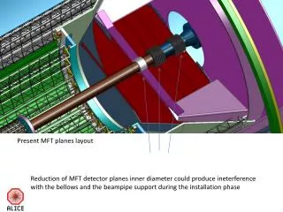
Present MFT planes layout
Present MFT planes layout. Reduction of MFT detector planes inner diameter could produce ineterference with the bellows and the beampipe support during the installation phase. 16.5mm. 100mm. 16.5mm ( vertical movement toto be done in less the 40mm-space between two bellow ).

Present MFT planes layout
E N D
Presentation Transcript
Present MFT planes layout Reductionof MFT detector planesinnerdiametercould produce ineterferencewith the bellows and the beampipesupportduring the installationphase
16.5mm 100mm
16.5mm (verticalmovement toto bedone in less the 40mm-space betweentwobellow) D=54mm D=60mm D=40mm Planesbetweeenbellows 54 mm diameterhole detector planeneedstoclear 60mm Bellowsdiameter (and 60mm diameter BP Al section)
Outer layers lay-out studies Option 1 to be compared with CDR radius 200, 220, 410, 430 Layersoverlap Overlap azimuth Layer 4=2.25 Layer5=2.33 Layer6=2.38 Layer7=2.31
Outer layers Geometrical lay-out studies Option 2 to be compared with CDR radius 200, 220, 410, 430 Layersoverlap Overlap azimuth Layer 4=2,11 Layer5=2,33 Layer6=2,30 Layer7=2,32
Outer layers Geometrical lay-out studies Option 3 to be compared with CDR radius 200, 220, 410, 430 Layersoverlap Overlap azimuth Layer 4=2.19 Layer 5=2.33 Layer 6=2.31 Layer 7=2.31
Outer layers Geometrical lay-out studies Option 4 to be compared with CDR radius 200, 220, 410, 430 Layersoverlap Overlap azimuth Layer 4=2.33 Layer 5=2.15 Layer 6=2.31 Layer 7=2.31
Outer layers Geometrical lay-out studies Option 5 to be compared with CDR radius 200, 220, 410, 430 Layersoverlap
Layer 6 & 7 Layer 4 & 5
SERVICES WAY OUT A-Side
NEW ITS INTEGRATION DETECTOR BARREL SERVICE BARREL MFT ITS LAYER 4,5,6,7 ITS LAYER 1,2,3 CAGE BEAM PIPE TPC OD= 1130mm CAGE OD= 1100mm MFT OD= 1030mm ITS OUT BARREL OD= 920mm