Diagnostic Imaging Primer
Diagnostic Imaging Primer. 3 Hour introduction to curricular thread Sean Collins Fall 2010. Outline ( Topic). Purpose of primer & thread Objectives of primer Required readings Underlying message General Principles & Plain films Computed Tomography Intro Magnetic Resonance Intro

Diagnostic Imaging Primer
E N D
Presentation Transcript
Diagnostic Imaging Primer 3 Hour introduction to curricular thread Sean Collins Fall 2010
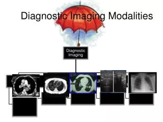
Outline (Topic) • Purpose of primer & thread • Objectives of primer • Required readings • Underlying message • General Principles & Plain films • Computed Tomography Intro • Magnetic Resonance Intro • Diagnostic Ultrasound Intro
Purpose of primer & thread • Primer – plant a seed of understanding of diagnostic imaging that will grow throughout many additional DPT courses during your three years in the program • Thread – To meet practice expectations regarding the integration of diagnostic imaging into physical therapy practice
Purpose of primer & thread • There are many threads throughout your DPT education. Everything you learn about examination, evaluation and intervention is technically a thread through the curriculum (MMT, ROM, Endurance, Functional mobility) • What makes Diagnostic Imaging different? • Increased use in practice is relatively new • Response to increased availability & ease of communication • Inclusion into PT education is therefore relatively new • No single course in the curriculum “owns” the material (neither do we have a course on MMT)
Objectives of primer • Explain the underlying logic of diagnostic imaging by x-rays, CT scan, MRI and Diagnostic ultrasound • How do these technologies create an image • What leads to “lightness” or “darkness” in the image • Understand visually the transformation of three-dimensional anatomy into two-dimensional imaging anatomy (Carried over into Anatomy & Neuroanatomy course) • Define basic terms and describe basic procedures of covered diagnostic imaging methods • Explain sources of variation in diagnostic images (if presented with two images – explain how they are different and propose why)
Required Readings McKinnis LM. Fundamentals of Musculoskeletal Imaging, 3rd Edition, 2010, FA Davis Reviewed in Primer – Chapters 1, 4, 5, 6 For Med/Surg Orthopedics Chapters 2 & 3
Underlying message Variation in images is obvious for: Different anatomical sites Different angles / planes of view Variation in images is also caused by: 1. Method of imaging – x-rays vs. computer modified images vs. proton signals vs. sound wave reflections 2. Interaction of method of imaging & different tissues You are looking at a 3d structure in 2d – even if there is a 3d reconstruction – your film or screen is only 2d
General Principles & Plain films(x-rays) • Radiation – energy transmitted through space of matter • Higher energy (x-ray, gamma ray) ionize atoms in matter • Ionization can disrupt life processes • Diagnostic radiography uses short wavelength ionizing electromagnetic radiation (therapeutic radiation uses shorter wavelengths that overlap with gamma rays)
Plain film process • Collimator controls size & shape of x-ray beam • X-ray beam passes through patient and undergoes attenuation • Attenuation is a reduction in # of x-ray photons in the beam due to interaction with matter and lose of energy through either scattering or photo-electric absorption • Remnant radiation emerges from patient & contains an aerial image of patient • Remnant radiation is captured by an image receptor • Captured image is “latent” until processed
Air (gas) Fat Water (muscle & soft tissue) Bone
Scatter of the beam will result in lower contrast Biederman, 2006
Need 2 films – perpendicular to one another to gather accurate information
AP View Viewed as if standing in front in anatomical position Markers: R – right L – left INT – introta. EXT ext rota WTB or ERECT – standing DECUB – recumbant INSP, EXP
Computed Tomography Intro • CT uses x-rays • Same radio densities as plain films (but not as impacted by other tissues) • Difference: • CT creates images based on cross-sectional slices created by up to 1000 projections from different angles • Tighter field of view via collimators that determine slice thickness
CT Scan Types 3D CT • Can be rotated “in space” on the computer screen – multiplanar reconstruction (MPR) • These images are not adequately viewed in the printed format
CT Scan Types CT Myelogram • Myelogram is most commonly performed with CT (as opposed to conventional radiographs) • The injection increases radiolucency or radioopacity of structures CT myelogram at C4-C5 – injection allows radioopacity of spinal canal
CT Scan – Selective Windowing • Windowing refers to the range of radio densities emphasized in the image • Bone Window (top) • Soft tissue – allows reader to distinguish between muscles and the fat between them • 1. Glut Medius • 2. Glut Maximus • 3. Fat between
CT Scan Imaging Artifacts • Hardening: as photons in the x-ray beam pass through structures such as the skull the beam becomes “harder” because they are absorbed more readily. Leads to dark bands in the image between radiopaque areas • Metals: lead to streaking that can present as bright lines in the image extending radially from the metal • Motion: movements can lead to shading or streaking. Faster scan times reduce the prevalence of motion artifacts
CT Scan Pros & Cons Best at: • Subtle or complex fractures • Degenerative changes • First in serious trauma • Spinal stenosis • Loose bodies in joints Less time & expense than MRI Accurate measure in any plane Less claustrophobia Limited in use for soft tissues due to reliance on radio density Relatively high radiation exposure
Contrast Enhanced • Contrast enhanced – a contrast medium is injected or ingested • Improves visualization by increasing contrast in areas with minimal inherence contrast • Can be radiopaque or radiolucent or dual • Angiography, mylography (myelogram)
Nuclear Imaging • Based on physiological or functional changes (usually activity) • Radionuclide that emits gamma rays • Gamma rays are detected by gamma camera that transforms into image • Static images, Whole body images, Dynamic images, Positron emission tomography (PET)
Magnetic Resonance Intro • Based on energy emitted from hydrogen nuclei (protons) following their stimulation by radiofrequency (RF) waves • Energy emitted varies according to tissue characteristics • Therefore, MRI can distinguish between different tissues • No “radio density” now – Signal Intensity “SI” • Greater SI is brighter; less SI is dark
Magnetic Resonance Phenomenon • MR is process by which nuclei, aligned in a magnetic field, absorb and release energy • While many molecules display MR, for all practical purposes MRI is based on signals from hydrogen in water molecules • Since hydrogen consists of 1 proton – the hydrogen nucleus is referred to as simply the proton in the context of MRI
MR Phenomenon • First protons are aligned by a strong magnetic field • A pulse of RF waves is applied at right angles to longitudinal magnetization • The pulse alters the alignment to a transverse plane, and the energy absorbed in the process brings them to a higher energy state: transverse magnetization • As the protons realign energy is released – this induces a current that gives rise to the data for creating the MRI
1. Aligned in magnetic field (longitudinal)2. RF wave3. Altered alignment (transverse, E increased)4. Gradually return to alignment (E release)
T1 & T2 Phenomenon • T1 & T2 are different processes related to the return of the alignment to the main magnetic field • T1 – time it takes for protons to gain longitudinal magnetization (T1 Recovery) • T2 –protons lose their transverse magnetization (T2 Decay) Two sides of same coin – but different processes MRI uses this to create different images that feature different tissues based on the protons response to the RF wave TR = time to repetition (time to repeat RF wave) TE = time to echo (time at which the signal is captured)
T1 Recovery • Protons lose energy to surrounding molecules • Time of return differs for different tissues • Faster recovery (shorter times – short T1) results in stronger signals from the protons of that tissue
T2 Decay • Transverse magnetization decays because of a loss of phase coherence, owing to interaction between protons • Slower decay – stronger signal recorded at end of the process
T1 & T2 Weighted Imaging T1 Weighted • Short TR and TE • Signal caught early when difference in relax characteristics for fat has higher SI • Good anatomical detail T2 Weighted • Long TR and TE • Tissues that are slow to give up energy are imaged – such as water – therefore water has high SI • Particularly valuable for detecting inflammation
Image Information • Scout image • Weighting and/or TR and TE • Slice thickness (4-8 mm) • FOV (field of view) • Date, Time, facility, body part, plane
Protocols • Combination of sequences • No standard protocols • Combination depends on the body part and the suspected pathology • Two main categories of sequences • Spin echo (SE) such as T1 and T2 images • Gradient echo (GRE)
SE Sequences • Usually referred to as T1 – or T2 weighted with specific parameters stated • Fast SE – as it sounds – faster • Proton density (PD) • Long TR and short TE the contrast is primarily due to PD, tissues with higher PD have higher SI • SI is similar to T1, but has greater anatomical detail • Inversion recovery (STIR – short tau inversion) • Inversion pulse cancels out the signal from fat to further reduce its SI in T2 images
Biederman, 2006 For better example of differences see Figure 5-4 in McKinnis text
GRE Sequences RF wave is applied and only partly flips the magnetization field (0-90 degrees) and includes a variable flip angle Allows reformatting to any plane – not limited to orthogonal plan – so used for complex anatomy Overall: • Fast image acquisition • High resolution with thin slices • High contrast between fluid and cartilage
Use of Contrasts • Intravenous gadolinium-containing contrast agents • Gadnolium is a paramagnetic metal ion used for regular MRI, MR angiography (MRA) and MR arthrography
MRI Advantages / Disadvantages Advantages Disadvantages Expensive Not always available Long imaging times Longer operator time Larger slices than CT More problems with motion artifact Less resolution for bone Concern about metal implants • Greater contrast for soft tissue • Image organs surrounded by dense bone • No ionizing radition • Less false positives