Download
1 / 40
410 likes | 571 Vues
HD EIE 42075 88M -108MHz Phase Lock Loop FREQUENCY SYNTHSIZER WONG TANG PAAI DILLIAN 01111911D WONG WAI TING KENNETH 01901021D. Content Introduction Process Example Difficulties Problem Solving Achievement Improvement. Introduction. VHF phase Lock Loop frequency synthesizer

E N D
HD EIE 42075 88M -108MHz Phase Lock Loop FREQUENCY SYNTHSIZER WONG TANG PAAI DILLIAN 01111911D WONG WAI TING KENNETH 01901021D
Content • Introduction • Process • Example • Difficulties • Problem Solving • Achievement • Improvement
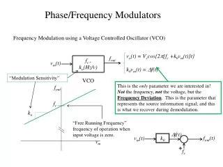
VHF phase Lock Loop frequency synthesizer Use the feedback and frequency comparator, to detect input frequency and send an error signal to request the change of frequency. When the input frequency is appropriate, the error signal will goes stables, and the frequency is locked. The frequency is actually generated by Voltage Control Oscillator.
Reference frequency 8051 Change the phase input into DC offset Variable Register R, N ÷ R=120 LPF Comparator ÷ N=1000 ~V RC tank circuit VCO & Buffer ~f
8051 Programming Voltage Control Oscillator Low Pass Filter Frequency synthesizer Phase Lock Loop
8051 12MHz R=120,N=1000 ÷ R=? LPF Comparator ÷ N=? ~V VCO & Buffer ~f
8051 12MHz 100kHz ÷ R=120 LPF ΔΦ 1 Comparator ÷ N=1000 105.8kHz 10V VCO & Buffer 105.8MHz
8051 12MHz 100kHz ÷ R=120 LPF ΔΦ 2 Comparator ÷ N=1000 103.8kHz 8V VCO & Buffer 103.8MHz
8051 12MHz 100kHz ÷ R=120 LPF ΔΦ 3 Comparator ÷ N=1000 101kHz 6V VCO & Buffer 101MHz
8051 12MHz 100kHz ÷ R=120 LPF ΔΦ 4 Comparator ÷ N=1000 99.5kHz 5.5V VCO & Buffer 99.5MHz
8051 12MHz 100kHz ÷ R=120 LPF ΔΦ 5 Comparator ÷ N=1000 100kHz 5.9V VCO & Buffer 100MHz
8051 12MHz R=120,N=1050 100kHz ÷ R=120 LPF ΔΦ 5 Comparator ÷ N=1050 95.2kHz 5.9V VCO & Buffer 100MHz
8051 12MHz 100kHz ÷ R=120 LPF ΔΦ 6 Comparator ÷ N=1050 100kHz 8.5V VCO & Buffer 105MHz
Programming Parasitic Capacitance Oscillation Wiring Grounding Connection
Grounding is the key parameter for determining the performance of PLL frequency synthesizer. If the grounding is handled inappropriate or not well enough for some critical point, some ac noise signal will be superimposed on the output signal, or modulate output signal with fm signal ruining the phase noise performance.
To minimize the noise effects, we should place a regular or an ac short circuit capacitor near the critical point, like supply power of chip. The ac fluctuation dual to current drop must be eliminated or at least minimized, we can ac grounding it immediately, making the wire as short as possible to minimize the antenna effect. Bold wire should be used to reduce the resistance, or use one ground plane to reduce the resistance with lesser complexity.
8.8 Grounding for chip place an ac short circuit capacitor near the critical point, like supply power of chip.
Each component will not influence each other, the fluctuation will not superimposed Use bold wire to reduce the resistance
Frequency Range 88M-108MHz Frequency Error ±6KHz Channel Spacing 100KHz Output Power -12dB Lock time 10ms Operating Voltage 20V Operating Current 28mA Technical Specification
Transient response of LPF (5/10)x 100 % = 50%overshoot 107MHz Control Voltage 15V 10V 100MHz Control Voltage
50%overshoot By Reducing the feedback gain of LPF 10~20%overshoot